

LED Lamp
a technology of led lamps and led chips, applied in the field of led lamps, can solve the problems of deteriorating color rendering properties of white led lamps in the red wavelength range, poor color rendering properties of conventional white led lamps including blue led chips, and poor color rendering properties of conventional led lamps. achieve the effect of improving color rendering properties
- Summary
- Abstract
- Description
- Claims
- Application Information
AI Technical Summary
Benefits of technology
Problems solved by technology
Method used
Image

Examples
embodiment 1
[0082]First, an LED lamp according to a first specific preferred embodiment of the present invention will be described with reference to FIG. 9A.
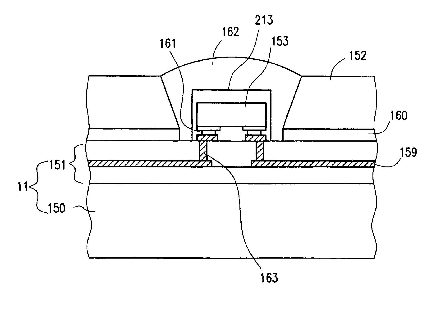
[0083]As shown in FIG. 9A, the LED, lamp preferably includes a substrate 91, an LED chip 92 bonded to the substrate 91, a resin portion 93 including a phosphor (or luminophore), and a filtering member 94.
[0084]In this preferred embodiment, the LED chip 92 is preferably flip-chip bonded to the principal surface of the substrate 91. Although not shown in FIG. 9A, interconnects are actually provided on the substrate 91 and electrically connected to the electrodes of the LED chip 92 mounted. The LED chip 92 is preferably supplied with a predetermined current or voltage from a lighting circuit (not shown) and through the interconnects on the substrate 91 to make the LED chip 92 emit the light.
[0085]The phosphor dispersed in the resin portion 93 absorbs, and is excited by, the emission of the LED chip 92, thereby producing fluorescence. The light...
embodiment 2
[0095]Hereinafter, an LED lamp according to a second specific preferred embodiment of the present invention will be described with reference to FIG. 9B. The LED lamp of this second preferred embodiment has almost the same configuration as the counterpart of the first preferred embodiment described above. In this preferred embodiment, however, the resin portion 93 and the filtering member 94 are arranged differently from the first preferred embodiment. Specifically, in the first preferred embodiment described above, a gap is provided between the resin portion 93 and the filtering member 94 as shown in FIG. 9A. In this second preferred embodiment on the other hand, the resin portion 93 and the filtering member 94 are in close contact with each other as shown in FIG. 9B. The reason is as follows. If the boundary 96 between the resin portion 93 and the filtering member 94 defines an interface between dissimilar materials, then the light will be refracted at the interface, thus decreasin...
embodiment 3
[0096]Hereinafter, an LED lamp according to a third specific preferred embodiment of the present invention will be described with reference to FIG. 9C. Unlike the LED lamp of the second preferred embodiment described above, the LED lamp of this preferred embodiment further includes a reflector 97 on the substrate 91.
[0097]The reflector 97 has at least one reflective surface for reflecting the light that has gone out of the LED chip 92 through the side surfaces thereof away from the substrate 91 (preferably perpendicularly to the principal surface of the substrate 91). This reflective surface is preferably provided so as to surround the side surfaces of the LED chip 92. If multiple LED chips 92 have been bonded to the substrate 91, then the reflector 97 preferably has multiple openings (through holes) for the respective LED chips 92. In that case, the inner walls of each opening of the reflector 97 function as the reflective surfaces. The inner walls (i.e., reflective surfaces) of ea...
PUM
 Abstract
Description
Claims
Application Information