Rotary electric machine for vehicle and control device thereof

a technology of electric machines and control devices, applied in the direction of magnetic circuit rotating parts, magnetic circuit shapes/forms/construction, safety/protection circuits, etc., can solve the problems of over-charged batteries, increased cost, and electric power exceeding electrical load

Active Publication Date: 2005-09-06
MITSUBISHI ELECTRIC CORP
View PDF6 Cites 31 Cited by
  • Summary
  • Abstract
  • Description
  • Claims
  • Application Information

AI Technical Summary

Problems solved by technology

However, in a generator with this kind of construction, even when no field current is passed and the generator operates with the magnetic flux of the permanent magnets only, at high speeds, and when the electrical load is small, it sometimes happens that electrical power exceeding the electrical load is generated, and the battery becomes over-charged and fails or an abnormal voltage is applied to electrical loads and causes them to fail.
In the examples of related art described above, with the technology disclosed in Patent Document 1, because a clutch is provided on the generator, increased cost is unavoidable, and, around the predetermined speed at which the clutch goes OFF the clutch comes ON and goes OFF repeatedly so that there remains problem of durability.
And, the technology disclosed in Patent Document 2 puts a limit on the output characteristic.
In particular, when this generator is used as a synchronous motor and made a charging generator cum starter motor, the excitation current becomes large, and when the claw pole type rotor core is manufactured by plastic deformation the residual magnetism also becomes large and output suppression at high speeds becomes difficult, and there remains a danger of the battery becoming over-charged.

Method used


Image

  • Rotary electric machine for vehicle and control device thereof
  • Rotary electric machine for vehicle and control device thereof
  • Rotary electric machine for vehicle and control device thereof

Examples


Embodiment Construction

[0026]First Preferred Embodiment

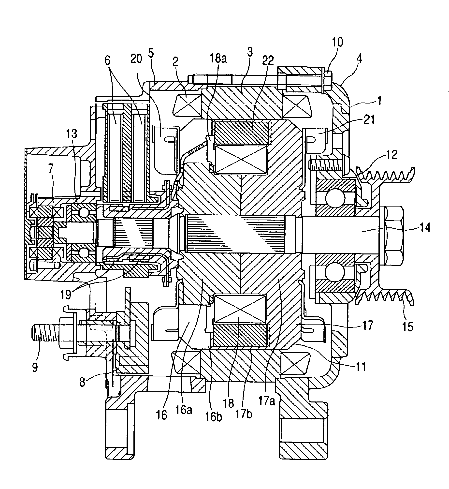
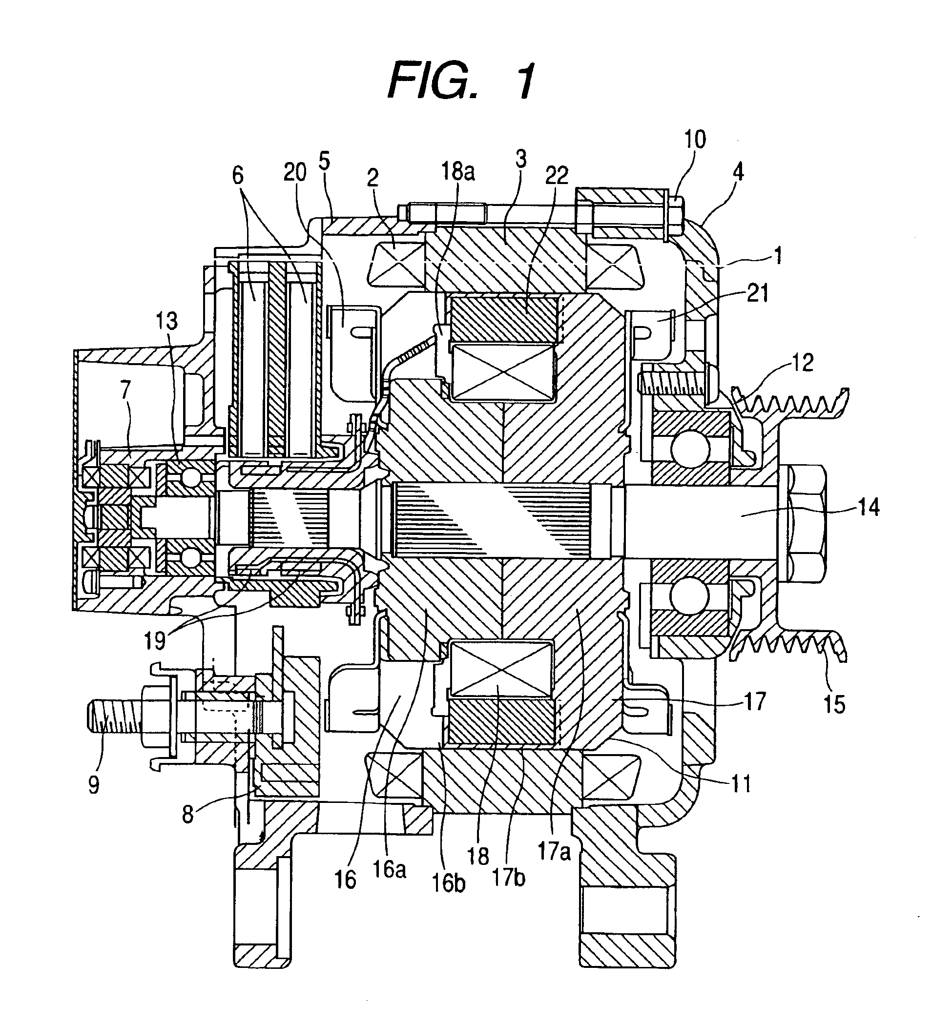
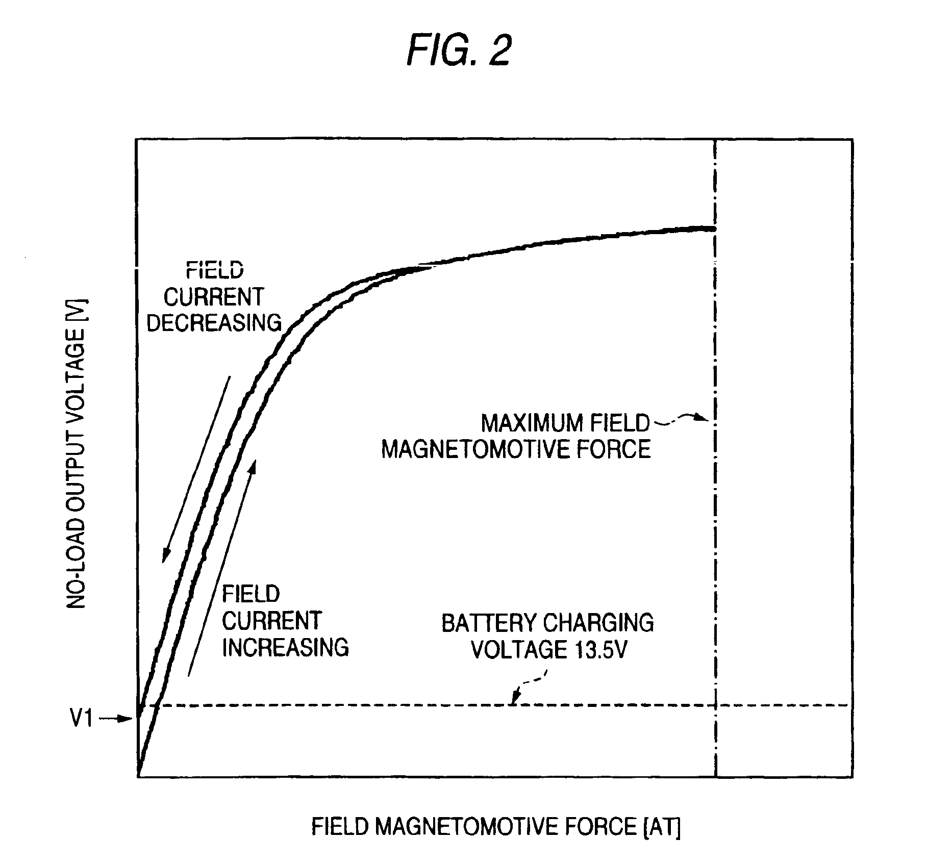
[0027]FIG. 1 is a sectional view showing the construction of a rotary electric machine for a vehicle according to a first preferred embodiment of the invention, and FIG. 2 is a characteristic chart showing a relationship between the magnetomotive force of a field and an output voltage. In FIG. 1, a stator 1 of a rotary electric machine for a vehicle is made up of an armature core 3 having an armature coil 2, and brackets 4 and 5 supporting the armature core 3 from the left and right. A brush holder 6, a sensor 7 for detecting angular position, a board 8 carrying a rectifier (not shown) for rectifying the output of the armature coil 2 and a voltage regulator (not shown) for controlling an output voltage, and a terminal 9 are provided on the bracket 5, and the armature core 3 and the brackets 4 and 5 are integrated by bolts 10.

[0028]A rotor 11 is made up of a rotor shaft 14 supported on the brackets 4 and 5 by bearings 12 and 13, a pulley 15 attached to...


PUM


Abstract

The rotary electric machine includes an armature core constituting a stator having an armature coil for charging a vehicle battery with its output voltage; rotor cores disposed inside the armature core with a predetermined gap therebetween and made up of magnetic pole parts formed as claw poles so that adjacent magnetic poles are different and cylindrical parts carrying a field coil; and permanent magnets provided in the magnetic circuit of the rotor cores for supplying magnetic flux along with the field coil to the armature core. The magnetizing force of the permanent magnets with respect to the armature core is set so that at a predetermined speed the output voltage of the armature coil immediately after a field current passed through the field coil is returned to zero from the maximum magnetizing force exerted by the field current does not exceed the charging voltage of the battery.

Description

BACKGROUND OF THE INVENTION[0001]1. Field of the Invention[0002]This invention relates to a charging generator installed in a vehicle, or to a generator / motor for a vehicle, and to a control device thereof, and particularly to constructions for preventing over-charging of a vehicle battery.[0003]2. Background Art[0004]To cope with increased electrical loads in vehicles and to raise fuel economy by reducing weight, increased output and reduced size and weight are being required in charging generators for vehicles, and one way of meeting these requirements is to supplement the magnetic field of the generator with a magnetizing force provided by permanent magnets and thereby reduce leakage flux between the magnetic poles and increase effective flux and increase output. However, in a generator with this kind of construction, even when no field current is passed and the generator operates with the magnetic flux of the permanent magnets only, at high speeds, and when the electrical load i...

Claims


Application Information

Patent Timeline
Patent Type & Authority Patents(United States)
IPC IPC(8): H02J7/16H02K1/22H02J7/14H02P9/14H02K1/27H02K19/22
CPCH02J7/1492H02J7/166H02K11/048H02K21/044Y02T10/7005Y02T10/92Y02T10/70H02J7/16H02J7/0048H02J7/00302H02K11/05
Inventor FUJITA, MASAHIKOASAO, YOSHIHITO
Owner MITSUBISHI ELECTRIC CORP
Why Eureka
Try Eureka