Permanent magnet synchronous motor

a permanent magnet, synchronous motor technology, applied in the direction of magnetic circuit rotating parts, magnetic circuit shape/form/construction, windings, etc., can solve the problems of increasing the leakage magnetic flux between teeth, rotor magnets are not easily subjected to demagnetizing magnetic field, and stator edges may interfere with each other

Inactive Publication Date: 2005-09-06
PANASONIC CORP
View PDF15 Cites 39 Cited by
  • Summary
  • Abstract
  • Description
  • Claims
  • Application Information

AI Technical Summary

Problems solved by technology

Further, when polarities of the coil and rotor oppose each other, the rotor magnets are not easily subjected to the demagnetizing magnetic field.
Meanwhile, when La is too small, the leakage magnetic flux between teeth becomes greater.
However, edges of the stator may interfere with each other due to mold errors produced when divided cores are manufactured.
Meanwhile, when Lb is too large, the leakage magnetic flux to be shorted grows too large, thereby lowering the motor output.

Method used


Image

  • Permanent magnet synchronous motor
  • Permanent magnet synchronous motor
  • Permanent magnet synchronous motor

Examples


exemplary embodiment 1

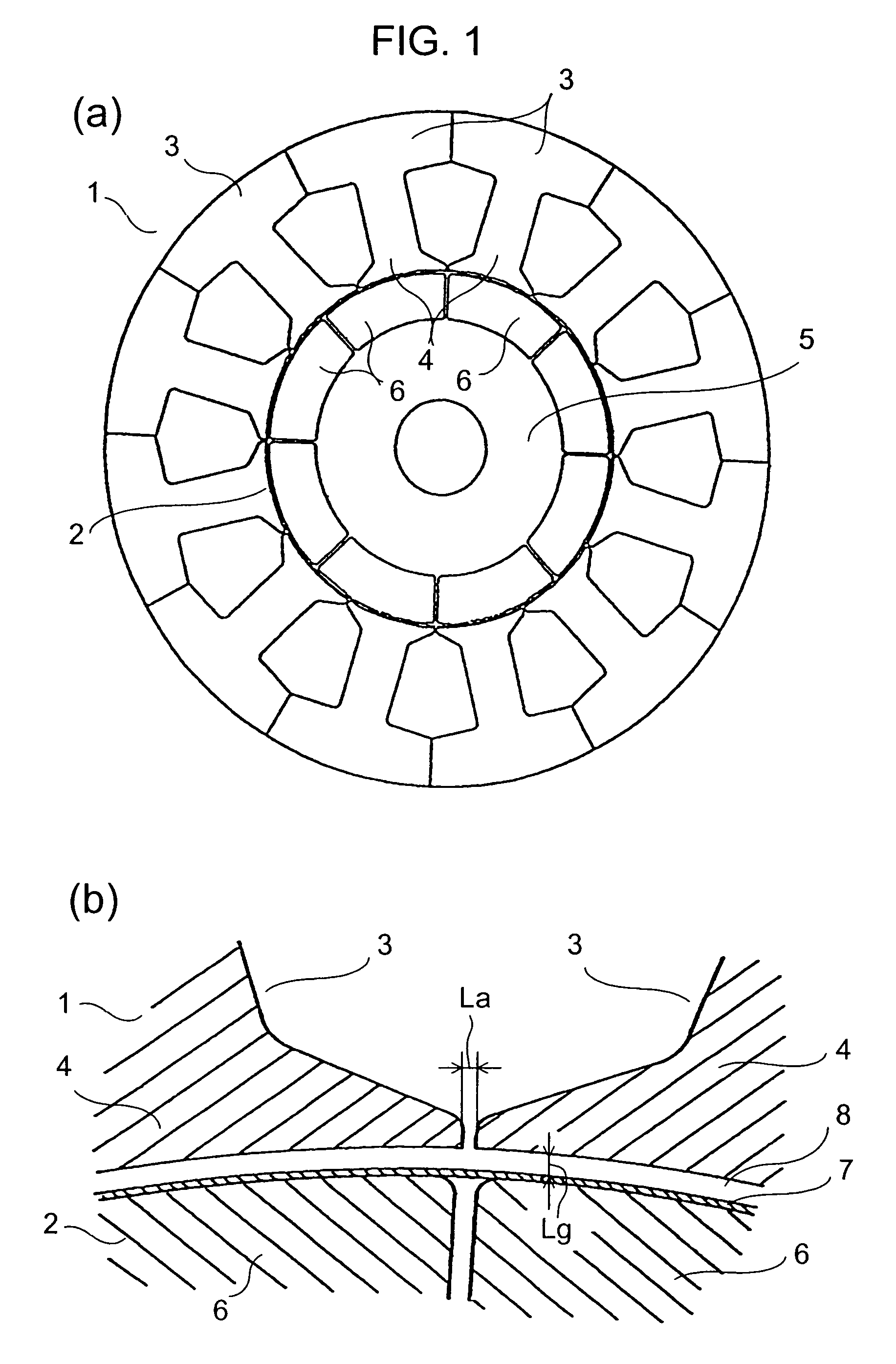
[0040]The first exemplary embodiment of the present invention is demonstrated hereinafter with reference to FIG. 1 and FIG. 2.

[0041]In FIG. 1, stator 1 comprises divided cores 3 in a quantity corresponding to a number of slots. Teeth 4 of respective divided cores 3 are wound with coils (not shown) independently, i.e., the concentrated winding method is employed. Rotor 2 comprises rotor core 5 formed of laminated silicon steel sheet and permanent magnets 6 made of plurality of ferrite magnets, where magnets 6 are fixedly mounted to the outer wall of rotor core 5. A rotary shaft (not shown) extending through and fixed to the center of rotor core 5 is journaled by a bearing. Hollow cylinder 7 made of stainless steel sheet is fit onto the outer wall of rotor 2, or a reinforcing tape is wound around the outer wall so that necessary strength against centrifugal force is obtained.

[0042]The motor shown in the drawing has four pairs of polarity (=n), rotor 2 has eight permanent magnets (=2 n...

exemplary embodiment 2

[0047]A permanent magnet synchronous motor in accordance with the second exemplary embodiment is demonstrated hereinafter with reference to FIG. 3 and FIG. 4. The like elements used in the first embodiment bear like reference marks, and the descriptions thereof are thus omitted here.

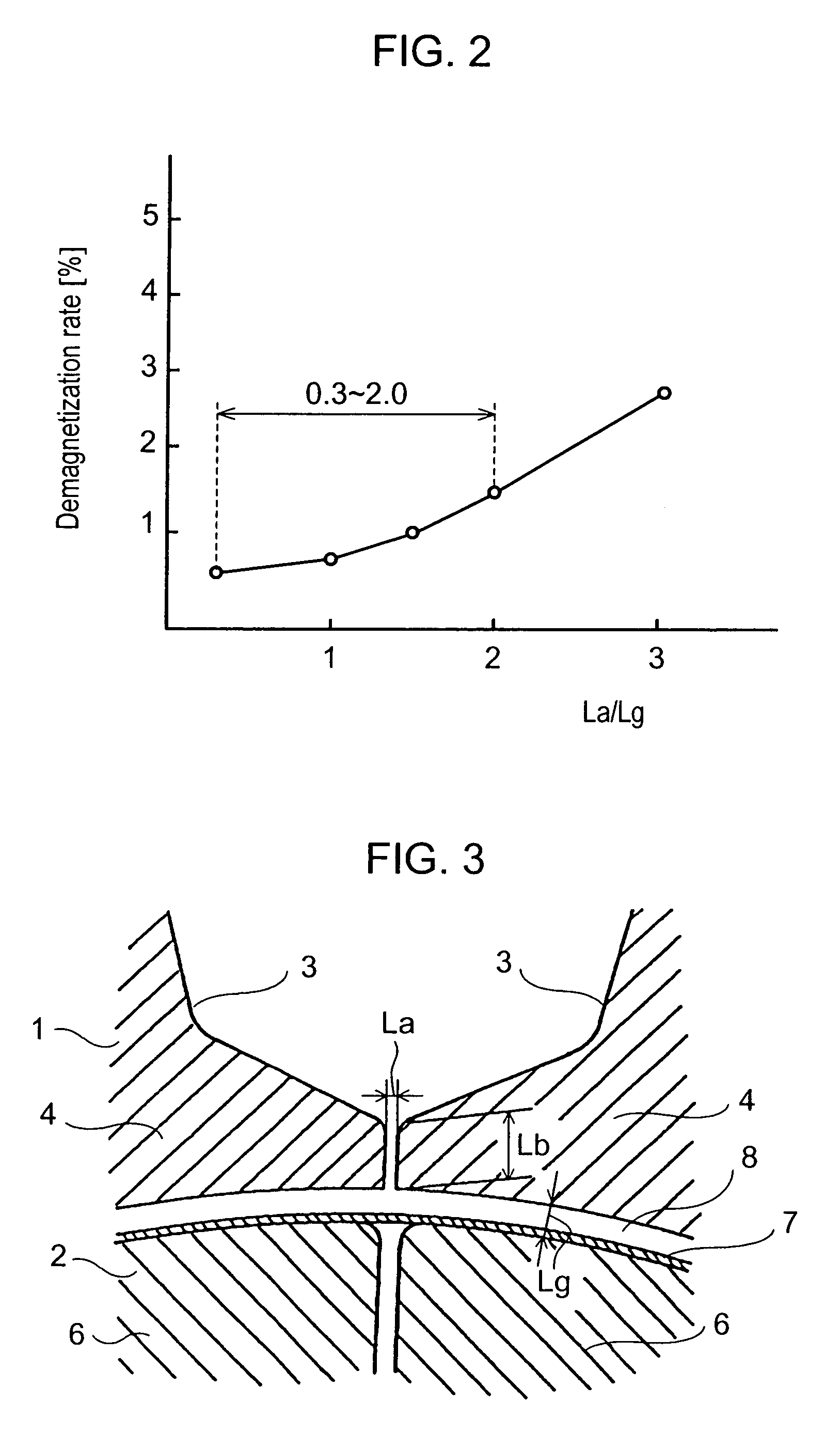
[0048]As illustrated in FIG. 3, La and Lb are set to meet the relations of:

0.3 Lg<La<2.0 Lg, and 2 Lg<Lb<5 Lg,

where La=clearance between teeth 4 and 4,[0049]Lb=depth of edge of tooth 4 of stator 1, and[0050]Lg=air gap 8 between stator 1 and rotor 2.

[0051]In the construction discussed above, in addition to the arrangements done in the first embodiment, tooth depth Lb is set at greater than two times the air-gap Lg, thereby further restraining the leakage flux from flowing toward rotor 2. As a result, the withstanding force against the demagnetization can be increased. Since Lb is set at less than 5 Lg, the leakage flux shorting between teeth 4 and 4 does not grow too much, so that the motor o...

exemplary embodiment 3

[0054]A permanent magnet synchronous motor in accordance with the third exemplary embodiment is demonstrated hereinafter with reference to FIG. 5.

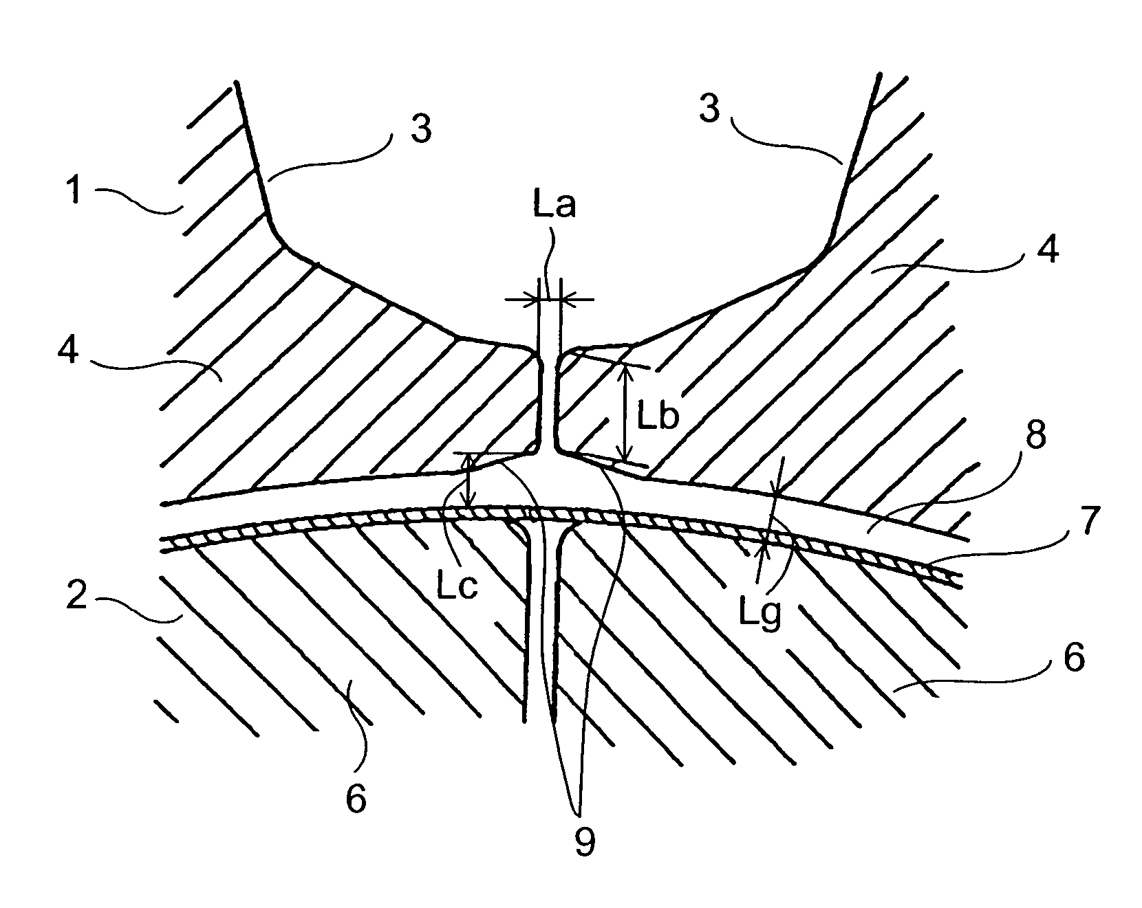
[0055]In FIG. 5, in addition to the arrangements done in the second embodiment shown in FIG. 3, parts of the edges facing each other of the adjacent teeth 4 and 4 are cut away on their rim sections that face (i.e., are closest to) rotor 2, and the cut-away section is called bevel 9. (A clearance between tooth edge 4 and rotor 2 is referred to as Lc.)

[0056]Bevel 9 can be provided only on the trailing-side edge with respect to the rotating direction of the rotor 2 out of the edges of teeth opposing each other.

[0057]The air gap on the edges of teeth 4 can be enlarged by providing bevel 9, and this can restrain the demagnetizing magnetic flux from flowing toward the rotor. As a result, the same effect is obtainable.

[0058]At the edge of tooth 4 where the rim side facing the rotor 2 has been cut away, the other side facing away (farthest) from t...


PUM


Abstract

The present invention provides a permanent-magnet-synchronous-motor having a stator with concentrating windings with the following structure so that permanent magnet (6) is hard to subjected to demagnetization magnetic field: 0.3 Lg<La≦2.0 Lg, where La is a clearance between teeth of stator (1), and Lg is an air-gap between stator (1) and rotor (2), and yet outer walls of both ends of the permanent magnet (6) disposed within rotor (2) in a rim direction are tapered toward inside from a rotor rim in a radial direction and thus form recessed section on the outer walls of the magnets. As a result, withstanding force against demagnetization is expected to increase.

Description

[0001]This application is a continuation-in-part application of International Application PCT / JP98 / 03996, filed Sep. 7, 1998, which is hereby incorporated by reference.TECHNICAL FIELD[0002]The present invention relates to permanent magnet synchronous motors, and particularly relates to a permanent magnet synchronous motor having a stator with concentrated windings.BACKGROUND ART[0003]A high power permanent magnet synchronous motor, in general, uses numbers of teeth of a stator and employs a distributed winding method so that the composite magnetomotive force of this motor can approximately form a sine wave. Permanent magnets of the rotor of this synchronous motor employs magnets made of rare-earth material featuring a high density of magnetic flux as well as large withstanding forces against demagnetization. Further, a sensor detects a rotational phase of the rotor so that the current phase can be controlled responsive to a rotor position.[0004]However, the distributed winding metho...

Claims


Application Information

Patent Timeline
Patent Type & Authority Patents(United States)
IPC IPC(8): H02K1/27H02K3/04H02K21/16
CPCH02K1/278H02K21/16H02K1/146
Inventor MURAKAMI, HIROSHIHONDA, YUKIOYOKOTE, SHIZUKAASANO, YOSHINARIWADA, YUKITOSHIHIROSE, HIDEOMATSUSHITA, YASUAKI
Owner PANASONIC CORP
Why Eureka
Try Eureka