Monocentric autostereoscopic optical apparatus with a spherical gradient-index ball lens

a technology of gradient-index ball and autostereoscopic optical apparatus, which is applied in the direction of instruments, stereoscopic photography, projectors, etc., can solve the problems of observer apprehension, observer's head being in close proximity to a rapidly spinning surface, and design has considerable drawbacks, etc., to achieve high brightness, small footprint, and high contrast

Inactive Publication Date: 2005-09-06
EASTMAN KODAK CO
View PDF26 Cites 15 Cited by
  • Summary
  • Abstract
  • Description
  • Claims
  • Application Information

AI Technical Summary

Benefits of technology

[0037]It is an advantage of the present invention that it provides a compact arrangement of optical components, capable of being packaged in a display system having a small footprint.
[0038]It is a further advantage of the present invention that it allows high-resolution stereoscopic electronic imaging with high brightness and high contrast, with a very wide field of view. The present invention provides a system that is light-efficient and requires relatively low levels of light for projection.
[0039]It is an advantage of the present invention that it provides a solution for wide field stereoscopic projection that is inexpensive when compared with the cost of conventi

Problems solved by technology

While the Kintz design provides one solution for a truly autostereoscopic system having a wide field of view, this design has considerable drawbacks.
Among the disadvantages of the Kintz design is the requirement that the observer's head be in close proximity to a rapidly spinning surface.
Even with protective shielding, proximity to a rapidly moving surface could, at the least, cause the observer some apprehension.
In addition, use of such a system imposes considerable constraints on head movement.
It is also known that conflict between depth cues associated with “vergence” and “accommodation” can adversely impact the viewing experience.
It is known that there can be a temporary degradation of the observer's depth perception when the observer is exposed for a period of time to mismatched depth cues for vergence and accommodation.
While such a solution may be tolerable in the limited simulation environment disclosed in the Walker et al. patent, and may simplify the overall optical design of an apparatus, constraint of head movement would be a disadvantage in an immersion system.
However, this type of system is limited to small viewing angles and is, therefore, not suitable for providing an immersive viewing experience.
In addition, images displayed using such a system are real images, presented at close proximity to the observer, and thus likely to introduce the vergence/accommodation problems noted above.
The apparatus disclosed in the McKay article has limited field of view, due to the use of conventional projection optics and due to dimensional constraints that limit membrane mirror curvature.
This can result in undesirable distortion and other image aberration, constraining field of view and limiting image quality overall.
It is recognized in the optical arts that each of these requirements, by itself, can be difficult to achieve.
However, while the advantages of monocentric design for overall simplicity and for minimizing distortion and optical aberrations can be appreciated, such a design concept can be difficult to implement in an immersion system requiring wide field of view and large exit pupil with a reasonably small overall

Method used


Image

  • Monocentric autostereoscopic optical apparatus with a spherical gradient-index ball lens
  • Monocentric autostereoscopic optical apparatus with a spherical gradient-index ball lens
  • Monocentric autostereoscopic optical apparatus with a spherical gradient-index ball lens

Examples


Embodiment Construction

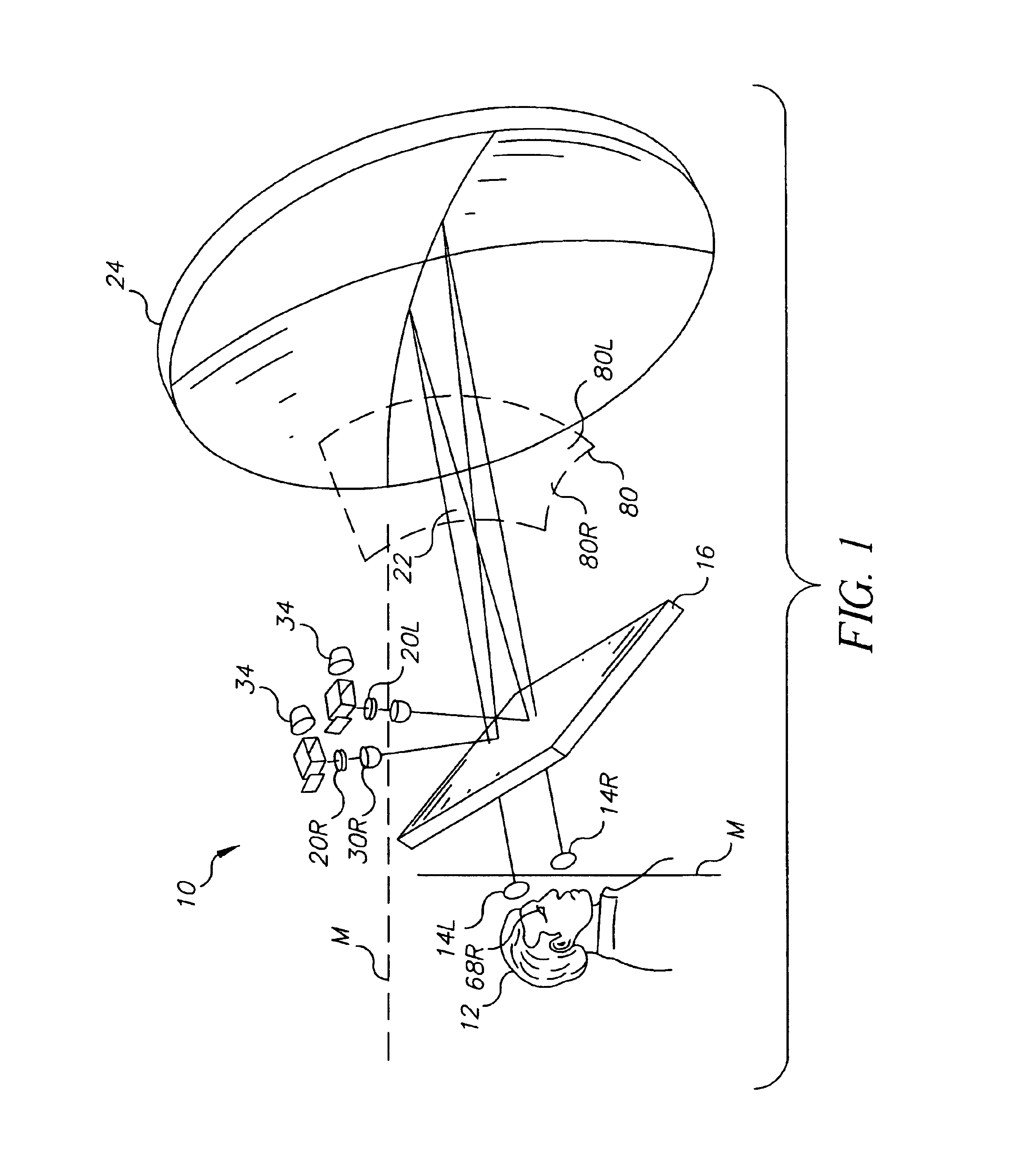
[0063]The present description is directed in particular to elements forming part of, or cooperating more directly with, apparatus in accordance with the invention. It is to be understood that elements not specifically shown or described may take various forms well known to those skilled in the art.

[0064]Referring to FIG. 1, there is shown a perspective view of an autostereoscopic imaging system 10. An observer 12 is typically seated in position to view a virtual stereoscopic image from left and right viewing pupils 14l and 14r. Optimal viewing conditions are obtained when left and right eye pupils 68l (not labeled in FIG. 1) and 68r of observer 12 are coincident with the position of left and right viewing pupils 14l and 14r.

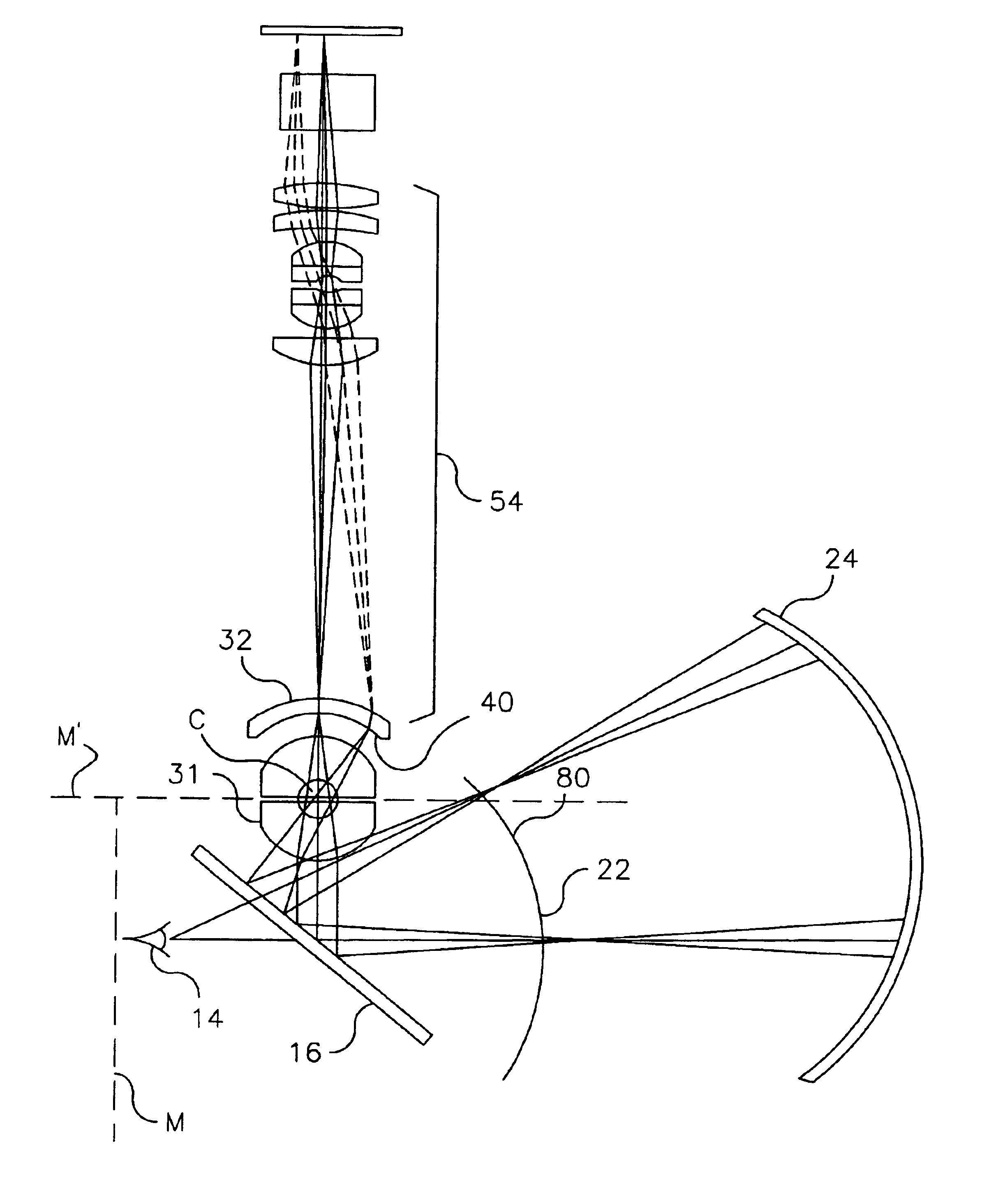
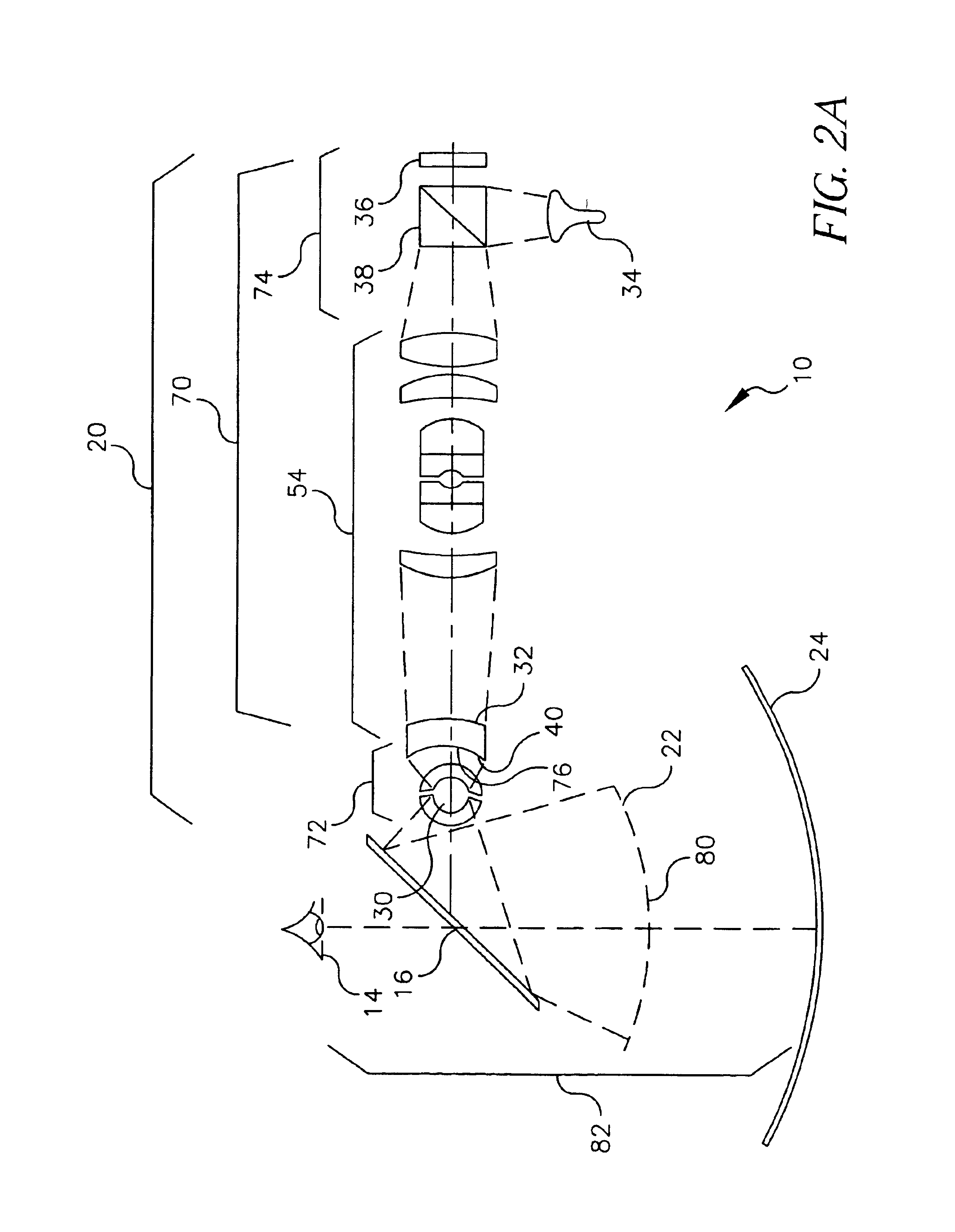
[0065]A right optical system 20r directs an image through a right ball lens assembly 30r to a beamsplitter 16. A right curved image 80r is formed at a front focal surface 22 of a curved mirror 24, so as to be located between right ball lens 30r and curved mirror...


PUM


Abstract

A monocentric autostereoscopic optical apparatus (10) for viewing a virtual image, electronically generated and projected on a curved surface. For each left and right image component, a separate optical system comprises an image generation system (70l, 70r) and projection system (72), the projection system comprising a spherical diffusive surface (40) and a spherical gradient-index ball lens assembly (31) to provide wide field of view. A monocentric arrangement of optical components images the ball lens pupil (48) at the viewing pupil (14) and essentially provides a single center of curvature (C) for projection components. Use of such a monocentric arrangement, diffusive surface (40), and ball lens (30) provides an exceptionally wide field of view with large viewing pupil (14).

Description

FIELD OF THE INVENTION[0001]The invention generally relates to autostereoscopic display systems for viewing electronically generated images and more particularly relates to an apparatus and method for a monocentric arrangement of optical components to provide a very wide field of view and large exit pupils.BACKGROUND OF THE INVENTION[0002]The potential value of autostereoscopic display systems is widely appreciated particularly in entertainment and simulation fields. Autostereoscopic display systems include “immersion” systems, intended to provide a realistic viewing experience for an observer by visually surrounding the observer with a 3-dimensional (3-D) image having a very wide field of view. As differentiated from the larger group of stereoscopic displays that include it, the autostereoscopic display is characterized by the absence of any requirement for a wearable item of any type, such as goggles, headgear, or special glasses. That is, an autostereoscopic display attempts to p...

Claims


Application Information

Patent Timeline
IPC IPC(8): G02B27/22G03B35/20G02B30/26H04N13/04
CPCG02B27/2235G02B27/225G02B30/26G02B30/35
Inventor LIANG, RONGGUANGKESSLER, DAVID
Owner EASTMAN KODAK CO
Why Eureka
Try Eureka