System and method for a quality of service in a multi-layer network element

Inactive Publication Date: 2005-09-06
SUN MICROSYSTEMS INC
View PDF7 Cites 115 Cited by
  • Summary
  • Abstract
  • Description
  • Claims
  • Application Information

AI Technical Summary

Benefits of technology

[0036]The switching element also includes a memory having at least one entry that stores information about forwarding decisions for the packet, wherein the entry is adapted to indicate whether packets associated with that entry should be counted. Memory access logic accesses the entry when an incoming packet associated with that entry arrives at the switchi

Problems solved by technology

The number of stations that can be interconnected through bridges is limited because traffic isolation, bandwidth, fault detecting, and management aspects become too difficult or burdensome as the number of end stations increases.
Routers, however, require intensive configuration, and may even require configuration activities at the end nodes.
Generally, as the size and complexity of a network increases, the network requires more functionality at the higher layers.
A single LAN is typically insufficient to meet the requirements of an organization because of the inherent limitations: (1) on the number of end stations that can be attached to a physical layer segment; (2) the physical layer segment size; and (3) the amount of traffic, which is limited because the bandwidth of the segment must be shared among all the connected end stations.
Bridges, unlike routers, forward packets based on data link addresses and thus cannot interpret hierarchical addresses.
Supporting this combination by building networks out of layer 2 network elements pro

Method used


Image

  • System and method for a quality of service in a multi-layer network element
  • System and method for a quality of service in a multi-layer network element
  • System and method for a quality of service in a multi-layer network element

Examples


Example

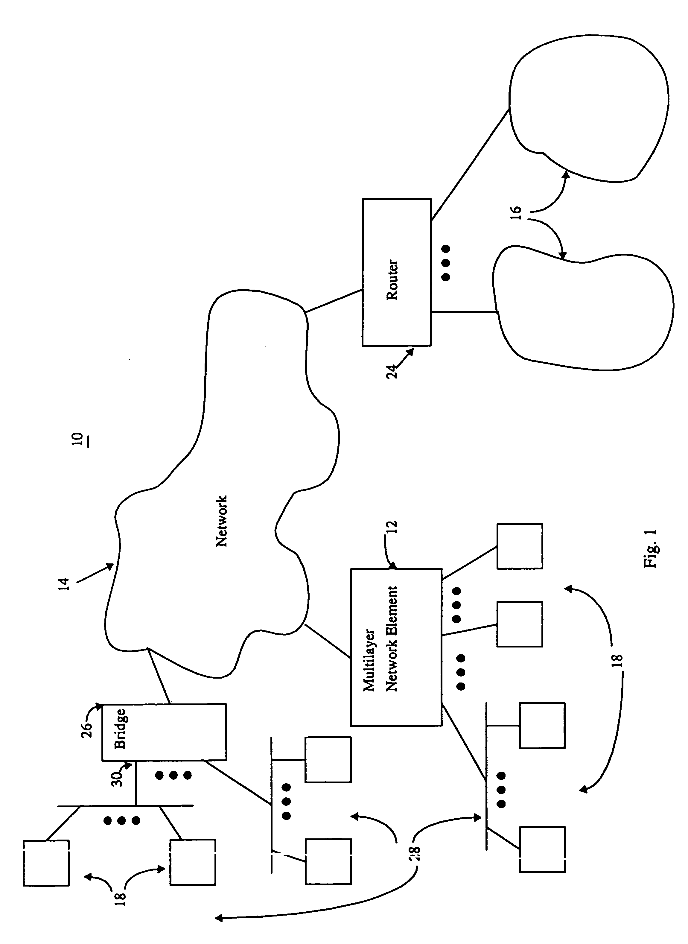
[0051]FIG. 1 illustrates a system incorporating a multi-layer network element according to the present invention. The system includes the multi-layer network element, various networks, end stations, routers, and bridges. By way of example and as broadly embodied and described herein, a system 10 incorporating a multi-layer network element 12 according to the present invention includes networks 14 and 16, end stations 18, router 24, bridge 26, and local area networks (LAN) 28.

[0052]The bridge 26 connects some of the LANs 28 and end stations 18 to the network 14 and to each other. The bridge 26 may be a conventional learning bridge. The bridge 26 keeps track of the addresses of the end stations 18 that transmit a packet showing up on one of ports 30 to the bridge 26. The end stations 18 may be any device capable of sending or receiving packets of information. Typically, the end stations 18 are personal computers, workstations, printers, servers, and / or any other device that can be con...


PUM


Abstract

A multi-layer network element for forwarding received packets from an input port to one or more output ports with quality of service. When output queues exceed or meet a threshold value below the queue's capacity packets are randomly discarded. When the queue becomes full, the network element determines which flow caused the queue to overflow. The priority of that flow is lowered. In a multicast packet, the packet may have different priorities at each output port. Scheduling of multiple output queues at each output port uses a weight round robin approach that allocates a weight portion of packets to transmit at each time interval. A packet is not interrupted during its transmission, even if the weight portion is met during a packet's transmission. The excess number of bytes transmited as a result of not interrupting the packet are accounted for in the next round.

Description

[0001]This is a continuation of application Ser. No. 08 / 885,258, filed on Jun. 30, 1997, that is now U.S. Pat. No. 6,094,435.FIELD OF THE INVENTION[0002]The present invention relates in general to packet forwarding within a network and, in particular, to a system and method for forwarding packets using multi-layer information.BACKGROUND OF THE INVENTION[0003]Communication between computers has become an important aspect of everyday life in both private and business environments. Networks provide a medium for this communication and further for communication between various types of elements connected to the network such as servers, personal computers, workstations, memory storage systems, or any other component capable of receiving or transmitting data to or from the network. The elements communicate with each other using defined protocols that define the orderly transmission and receipt of information. In general, the elements view the network as a cloud to which they are attached a...

Claims


Application Information

Patent Timeline
IPC IPC(8): H04L12/46H04L12/56
CPCH04L12/5693H04L47/10H04L47/15H04L47/20H04L47/21H04L47/24H04L47/2458H04L47/30H04L47/32H04L47/326H04L47/522H04L47/6215H04L47/6225H04L47/623H04L47/6265H04L49/90H04L49/901H04L49/9042H04L49/9047H04L49/9078H04Q2213/13103H04L47/50
Inventor HOFFMAN, DON
Owner SUN MICROSYSTEMS INC
Why Eureka
Try Eureka