
Sensor system for measuring and monitoring indoor air quality

a sensor system and indoor air technology, applied in the field of indoor air quality measurement, can solve the problems of poor indoor air quality, inability to work, and risk of developing non-migraine headaches, and achieve the effect of more accurate measuremen

Inactive Publication Date: 2005-09-06
AWI LICENSING
View PDF12 Cites 110 Cited by
  • Summary
  • Abstract
  • Description
  • Claims
  • Application Information

AI Technical Summary

Benefits of technology

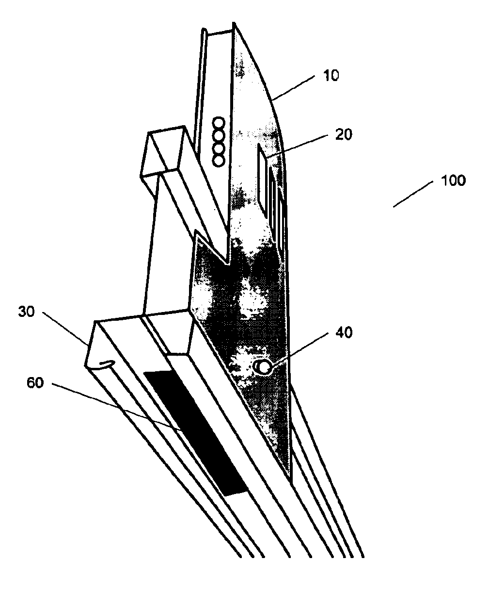
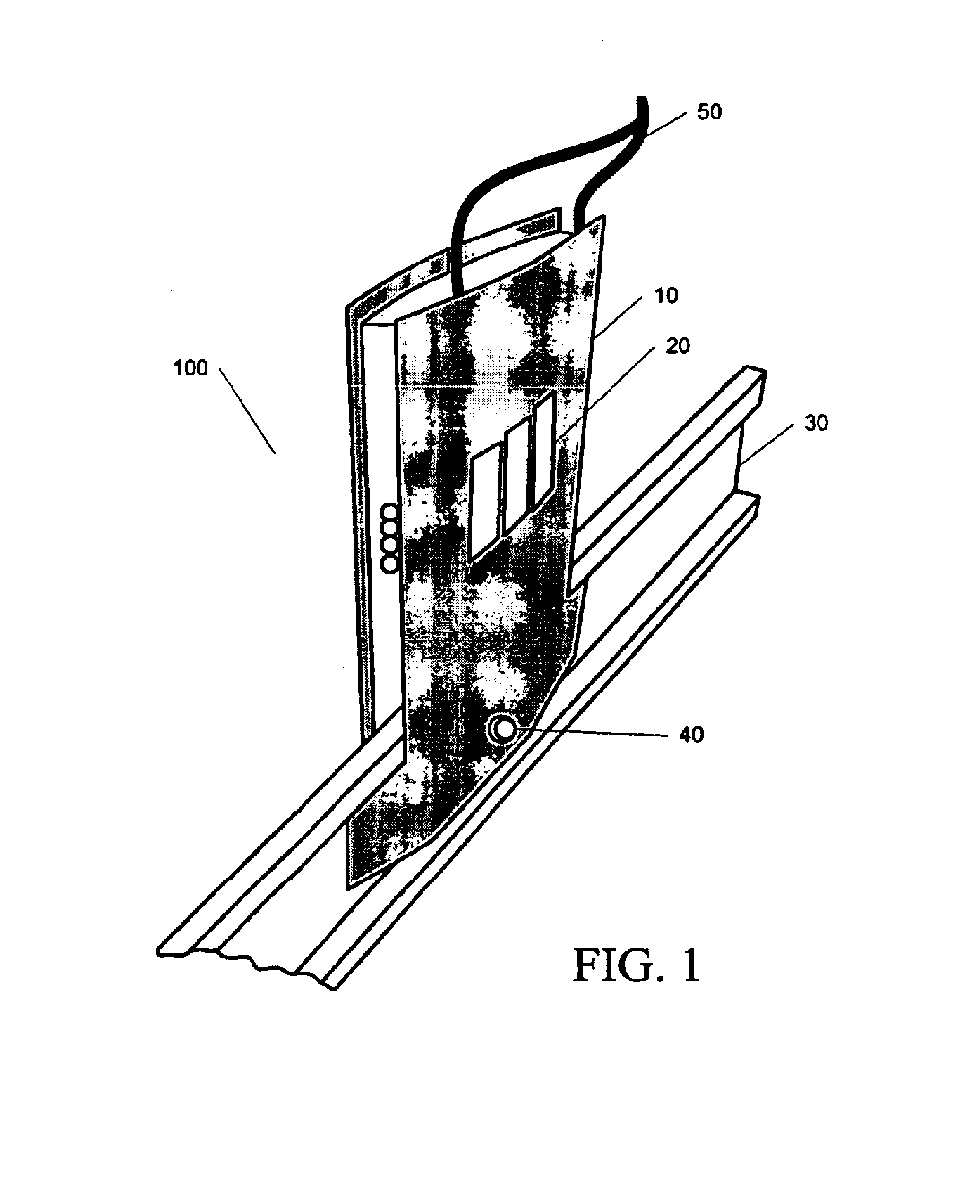
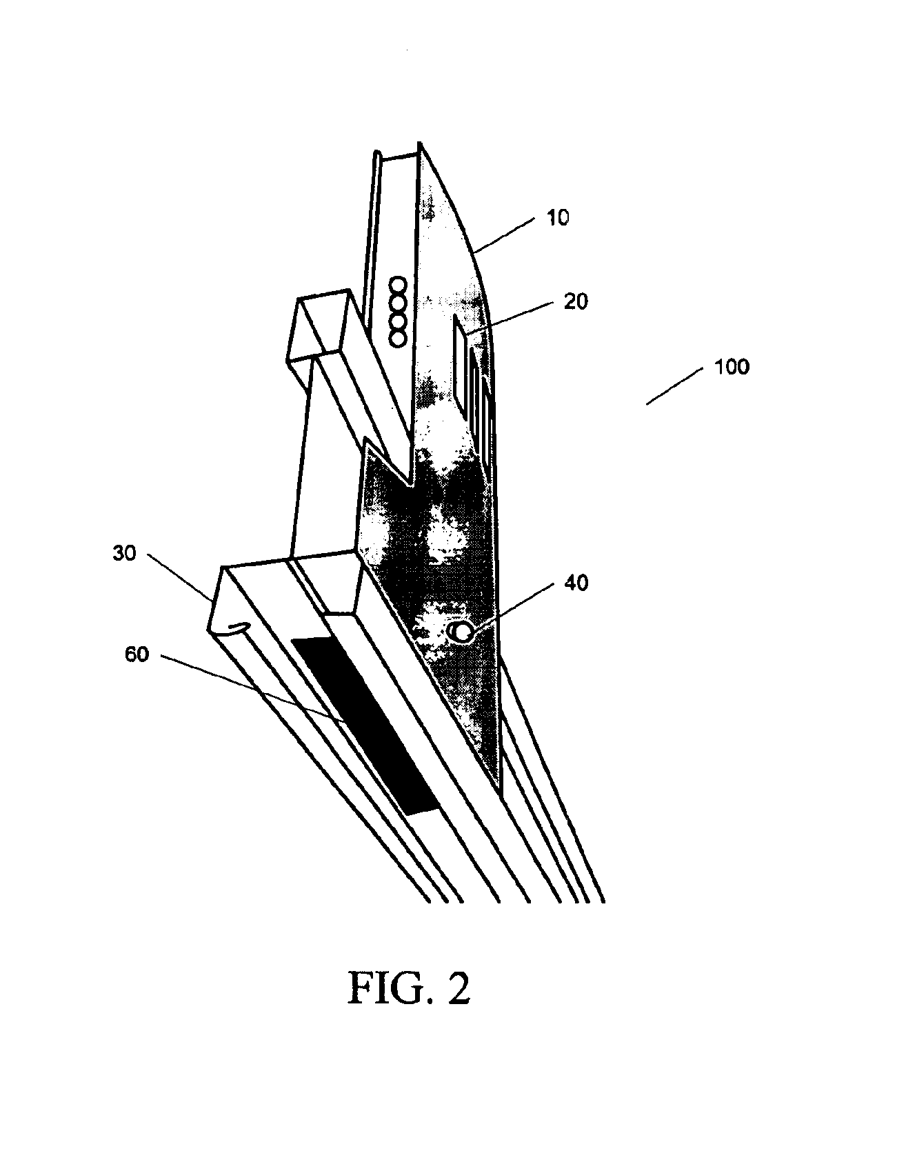
[0009]The present invention provides an apparatus for accurately sensing room conditions that is located in the air stream to the return air plenum. The apparatus is a combination of a temperature and VOC sensor. The sensor module is built into a ceiling grid system with the body of the sensor module extending into the return air plenum. The ceiling grid has a slot fabricated into its face which allows the air stream from the room to flow by the sensors on its way to the plenum. This enables both the temperature and the composition of the air to be monitored at the best location for n enclosed space.
[0012]The ceiling grid mounted pollution sensors along with at least one hand-held pollution concert operate in concert to measure and monitor air quality at any location within a building. Positioning a plurality of web-mounted pollution sensors above the ceiling panels provides for more accurate measurement of the air flow from enclosed spaces to the plenum above the ceiling grid system. The hand-held units can then be used to measure air quality in enclosed spaces not otherwise monitored by a web-mounted sensor device. The hand-held units can also be used to measure air quality at various points within larger enclosed spaces such as conference rooms, since there could be substantial variability.

Problems solved by technology

These factors include the source of contamination or discomfort; the heating, ventilating and air conditioning (HVAC) system not being able to control existing air contaminants and ensure thermal comfort; pollutant pathways connecting the pollutant source to the occupants with a driving force existing to move pollutants along the pathways; and the building occupants that are affected by the indoor air quality.
However, dilution can only work if there is a consistent flow of supply air that effectively mixes with the room air.
OSHA estimates that the excess risk of developing the type of non-migraine headache that may require medical attention or restrict activity, which has been associated with poor indoor air quality, is 57 per 1000 exposed employees.
The maximum amount of ventilation provided by an HVAC system may be limited, not only by the system's capacity, but also by the temperature and humidity of the outside air.
This results in inefficient use of building energy and waste.
However, temperature alone is not a sufficient indicator of indoor air quality.
New building construction techniques and materials significantly aggravate air quality problems because of the out gassing of undesirable substances, such as Volatile Organic Compounds (VOCs).
CO2 sensors can be used in addition to temperature sensors (i.e., thermostats), but CO2 sensors are expensive and therefore are used very infrequently.
Most pollution sensor devices are expensive laboratory equipment or stationary wall or ceiling mounted systems.

Method used


Image

  • Sensor system for measuring and monitoring indoor air quality
  • Sensor system for measuring and monitoring indoor air quality
  • Sensor system for measuring and monitoring indoor air quality

Examples


Embodiment Construction

[0019]The following description of the invention is provided as an enabling teaching of the invention in its best, currently known embodiment. Those skilled in the relevant art will recognize that many changes can be made to the embodiments described, while still obtaining the beneficial results of the present invention. It will also be apparent that some of the desired benefits of the present invention can be obtained by selecting some of the features of the present invention without utilizing other features. Accordingly, those who work in the art will recognize that many modifications and adaptations to the present invention are possible and may even be desirable in certain circumstances, and are a part of the present invention. Thus, the following description is provided as illustrative of the principles of the present invention and not in limitation thereof, since the scope of the present invention is defined by the claims.

[0020]FIGS. 1-2 depict two perspective views of the ceil...


PUM


Abstract

An apparatus for accurately sensing room conditions and positioned in the air stream to the return air plenum. The apparatus is a combination of a temperature and volatile organic compound (VOC) sensor. The sensor module is built into a ceiling grid system with the body of the sensor module extending into the return air plenum. The ceiling grid has a slot fabricated into its face which allows the air stream from the room to flow by the sensors on its way to the plenum. This enables both the temperature and the composition of the air to be monitored at the optimal location. A portable pollution sensor device that measures and monitors leading indicators of indoor air quality and the extent of pollution is used in conjunction with the ceiling grid mounted sensor modules. The portable device documents and benchmarks air quality both in buildings under construction and in existing buildings. The portable device is network-enabled so as to simultaneously transmit the data to various control devices. In addition to its use to monitor areas not otherwise covered by the ceiling grid mounted sensors, the hand-held sensor can be used during building construction to determine the best locations in the ceiling grid system for mounting of the fixed pollution sensors.

Description

BACKGROUND OF THE INVENTION[0001]The present invention relates generally to indoor air quality measurement, and more specifically to devices for monitoring the temperature and quality of air in building environments.[0002]Indoor air quality (IAQ) has become an important consideration in creating a satisfactory environment for today's building occupants, particularly in office buildings, schools, and health care facilities. Indoor air quality is a constantly changing interaction of a complex set of factors, which must be considered when looking for an indoor air quality problem. These factors include the source of contamination or discomfort; the heating, ventilating and air conditioning (HVAC) system not being able to control existing air contaminants and ensure thermal comfort; pollutant pathways connecting the pollutant source to the occupants with a driving force existing to move pollutants along the pathways; and the building occupants that are affected by the indoor air quality...

Claims


Application Information

Patent Timeline
Patent Type & Authority Patents(United States)
IPC IPC(8): G05B23/02
CPCG05B15/02F24F11/0017G05B2219/2642Y02B30/78F24F11/30F24F2110/50Y02B30/70F24F11/58F24F11/54
Inventor FRECSKA, SANDOR A.BISCHEL, WESLEY T. K.
Owner AWI LICENSING
Learn More