Method for monitoring a control system

a control system and monitoring technology, applied in the direction of electric programme control, program control, instruments, etc., can solve the problems of increasing the burden on the control station and information paths, reducing the efficiency of the control station, so as to achieve the effect of efficiently utilizing the capacity of the control station

Inactive Publication Date: 2005-09-06
CARL ZEISS MICROSCOPY GMBH +1
View PDF16 Cites 31 Cited by
  • Summary
  • Abstract
  • Description
  • Claims
  • Application Information

AI Technical Summary

Benefits of technology

[0011]Based on this prior art, it is the primary object of the invention to provide a control system in which the capacity of the control station can be utilized efficiently.

Problems solved by technology

A disadvantage in this previously known procedure consists in the fact that the transmission of commands to the slave, the initiation of adjusting processes and the inquiries and reports relating to the execution of the command takes a relatively long time.
The greater the quantity of communication units associated with a control system of this type and connected with the control station, the greater the burden on the control station and the information paths.
This procedure of continuous inquiry and response between the control station and slaves has accordingly proven to be disadvantageous with respect to the desired effective utilization of existing capacities of the control station and communications paths.

Method used


Image

  • Method for monitoring a control system
  • Method for monitoring a control system
  • Method for monitoring a control system

Examples


Embodiment Construction

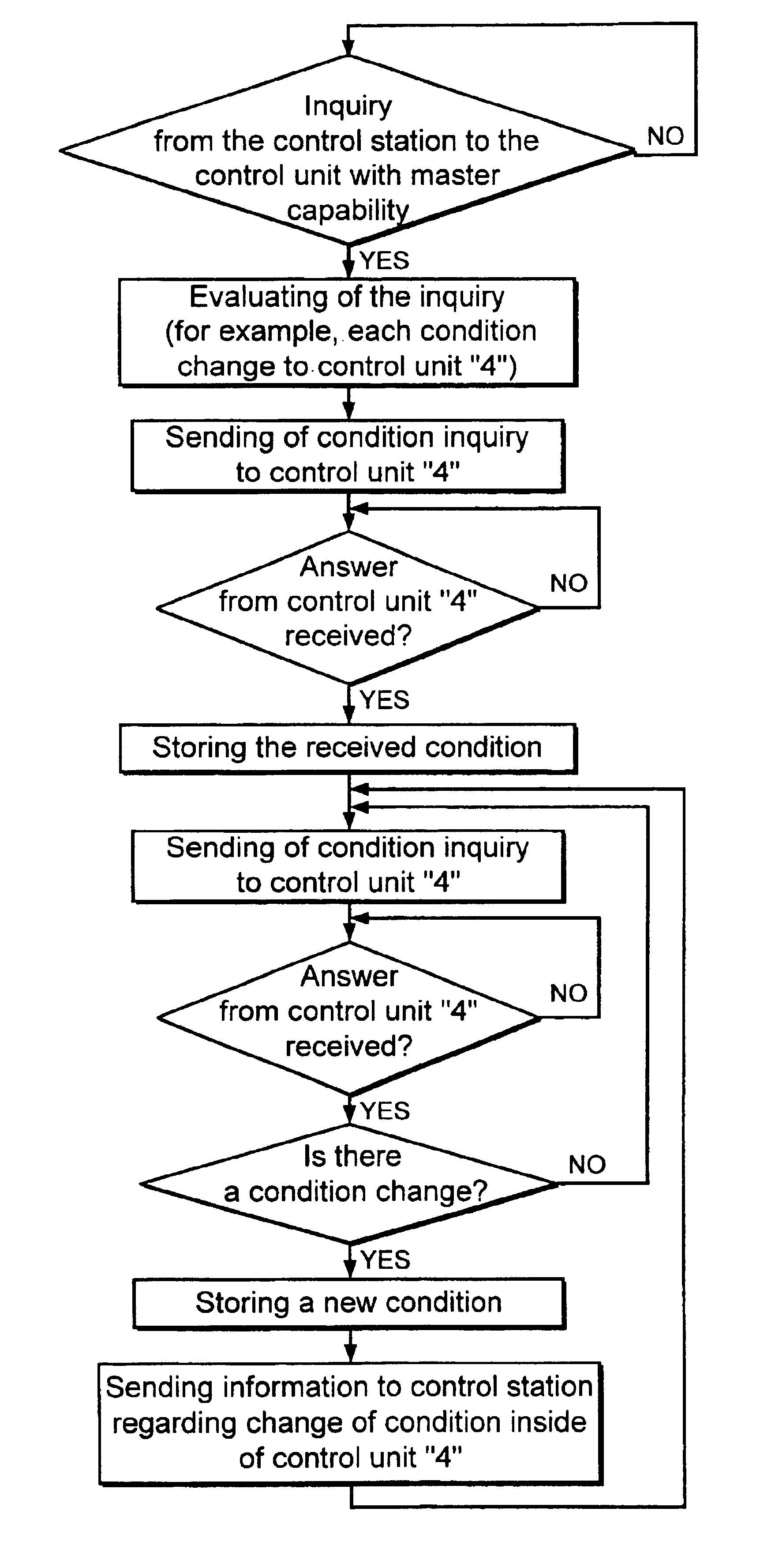
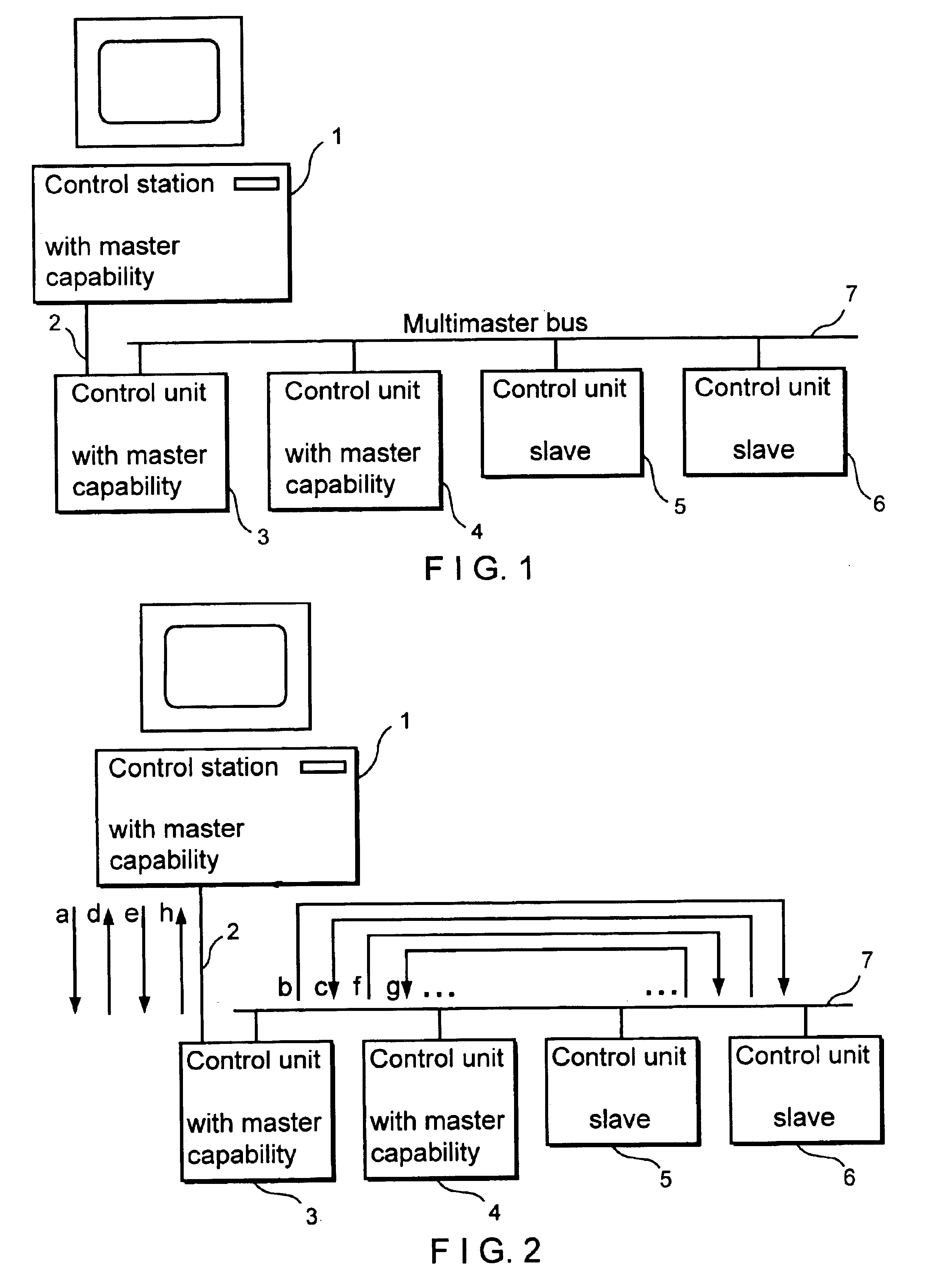
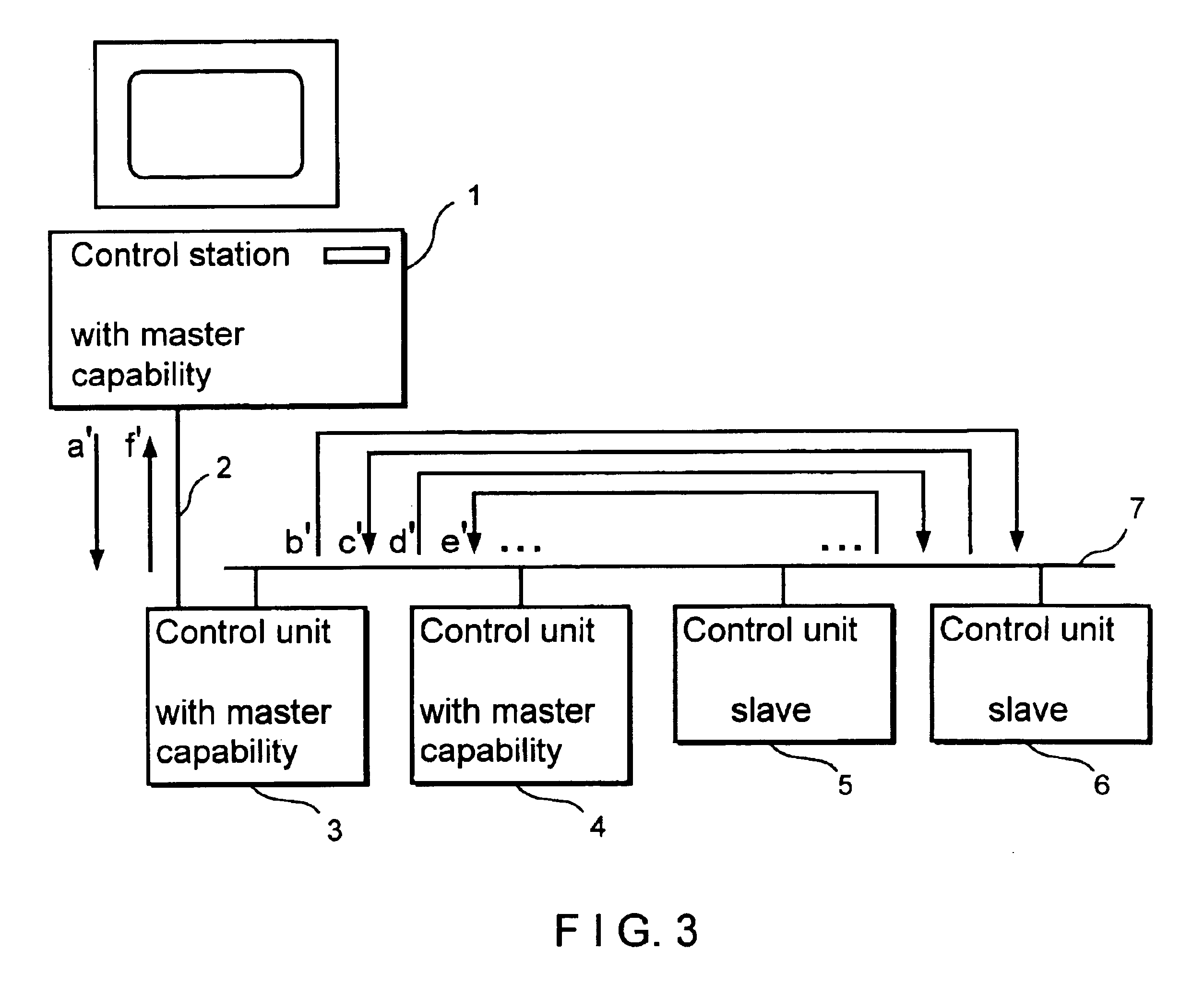
[0032]FIG. 1 shows a control system in which a control station 1 with master capability is connected via a two-point connection 2 to a control unit 3 with master capability. The control system comprises additional control units 4, 5 and 6, including, for example, a second control unit 4 with master capability and a control unit 5 and 6 without master capability. The control units 3 to 6 and all other control units which may possibly be associated with the control system, but are not shown, are linked via a multimaster bus 7.

[0033]The control units 5 and 6 without master capability are intelligent communications control circuits in the form of slaves which only receive commands from the control station 1, convey these commands as control commands to associated adjusting devices and inform the control station 1 of the execution, completion or progress of the adjusting command via the reverse information path.

[0034]It is also possible for the control units 3 and 4 with master capabilit...


PUM


Abstract

A method for monitoring a control system is disclosed comprising a plurality of control units, preferably for an optical measurement device or observation device. In a method of this type, it is provided that at least one control unit with master capability is incorporated in the communication between the control station and the rest of the control units and communicates with at least one of the control units for purposes of detecting status data and communicates with the control station for purposes of conveying the detected status data. In this way, polling for determining the current status is not the exclusive responsibility of the control station but, rather, can be taken over—at least partially or so as to be limited to determined processes—by the control unit with master capability enabled for this purpose. A control system for accomplishing the method is also disclosed.

Description

BACKGROUND OF THE INVENTION[0001]a) Field of the Invention[0002]The invention is directed to a method for monitoring a control system comprising a plurality of control units, preferably for an optical measurement device or observation device.[0003]b) Description of the Related Art[0004]In the case of complex measurement devices or observation devices, it is known to carry out the various device settings depending on the measurement or observation task at hand by means of actuating or adjusting units which are driven by electric motor. For example, commands are entered via a computer keyboard, evaluated in a computer serving as control station, and conveyed to the respective adjusting units. In high-quality microscope systems, for example, this relates to the adjustment of revolving lens turrets or objective turrets, field diaphragms and aperture stops, reflector turrets, variable condensers, cross-slide stages for X- and Y-displacement vertical to the microscope beam path, and for d...

Claims


Application Information

Patent Timeline
Patent Type & Authority Patents(United States)
IPC IPC(8): G05B19/042G05B19/04G05B15/02G02B21/00
CPCG05B15/02G05B19/0428G05B2219/21049G05B2219/2231G05B2219/25144G05B2219/25178
Inventor VOIGT, UWEMOEHLER, GUNTERGOETZ, BURKHARD
Owner CARL ZEISS MICROSCOPY GMBH
Why Eureka
Try Eureka