Self-cleaning flooring system

a self-cleaning and flooring technology, applied in the direction of functional valve types, machines/engines, water supply installation, etc., can solve the problems of difficult if not impossible maintenance of cleanliness, frequent spillage of waste products on kitchen flooring in restaurants, hotels,

Inactive Publication Date: 2005-09-13
DTS ENTERPRISES INC
View PDF14 Cites 80 Cited by
  • Summary
  • Abstract
  • Description
  • Claims
  • Application Information

AI Technical Summary

Problems solved by technology

The kitchen flooring in restaurants, hotels, institutions, and commercial food vending facilities in general is subject to frequent spillage from waste products.
Spilled waste products may create a sanitation hazard as a hot kitchen is a natural breeding ground for harmful bacteria that may be caught in tile grout, and around pipes, drains or other kitchen fixtures.
Because of the immovable nature of such kitchen fixtures, cleanliness is difficult if not impossible to maintain.
Daily cleaning of walls, counter tops, appliances and floors involves a great deal of hand labor consuming a considerable amount of time.
In addition, the waste products may create a health hazard in that spilled food products are often wet or sticky, creating a high risk that kitchen personnel may be injured in a fall.
Furthermore, spilled grease or oil creates a fire safety hazard requiring the cessation of all operations in the kitchen until the grease or oil is removed from the floor.
As may be expected, shutting down all kitchen operations in a restaurant or hotel may result in a significant loss of revenue.
Although the device addresses a few safety and sanitation issues mentioned above in that it provides a disposal means for fluid waste, the device lacks installation flexibility in that it must be custom fitted to a particular floor configuration.
In addition, the size of the grids and sub-floor are such that these components are too heavy and too large to be individually washed, either by hand or by mechanical means, such as in a commercial dishwasher.
However, a major drawback to the device is that a large portion of the subsurface of the flooring member is in direct contact with the moist support floor.
Although this device addresses some safety concerns in that it provides a non-slip surface upon which personnel may stand, the device is subject to the problems of mildew and degradation of the subfloor arising from captured water.
Furthermore, the device is not configured to be easily washable by hand or by mechanical means.

Method used


Image

  • Self-cleaning flooring system
  • Self-cleaning flooring system
  • Self-cleaning flooring system

Examples


Embodiment Construction

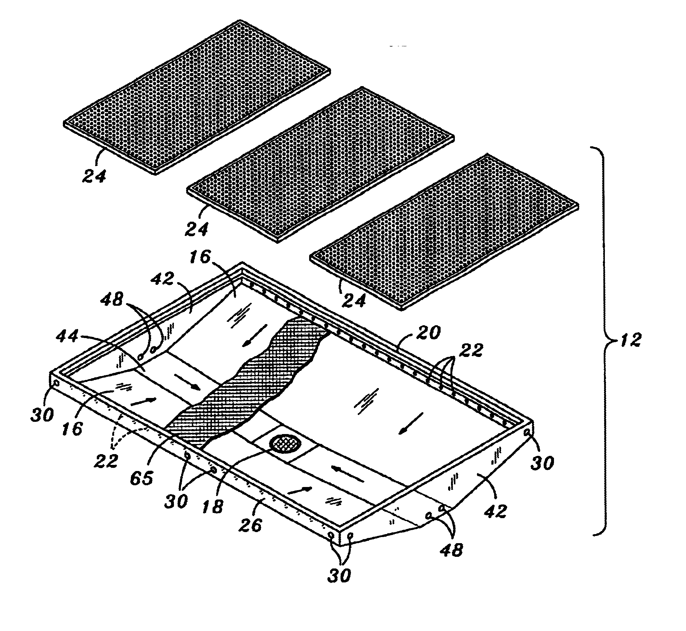
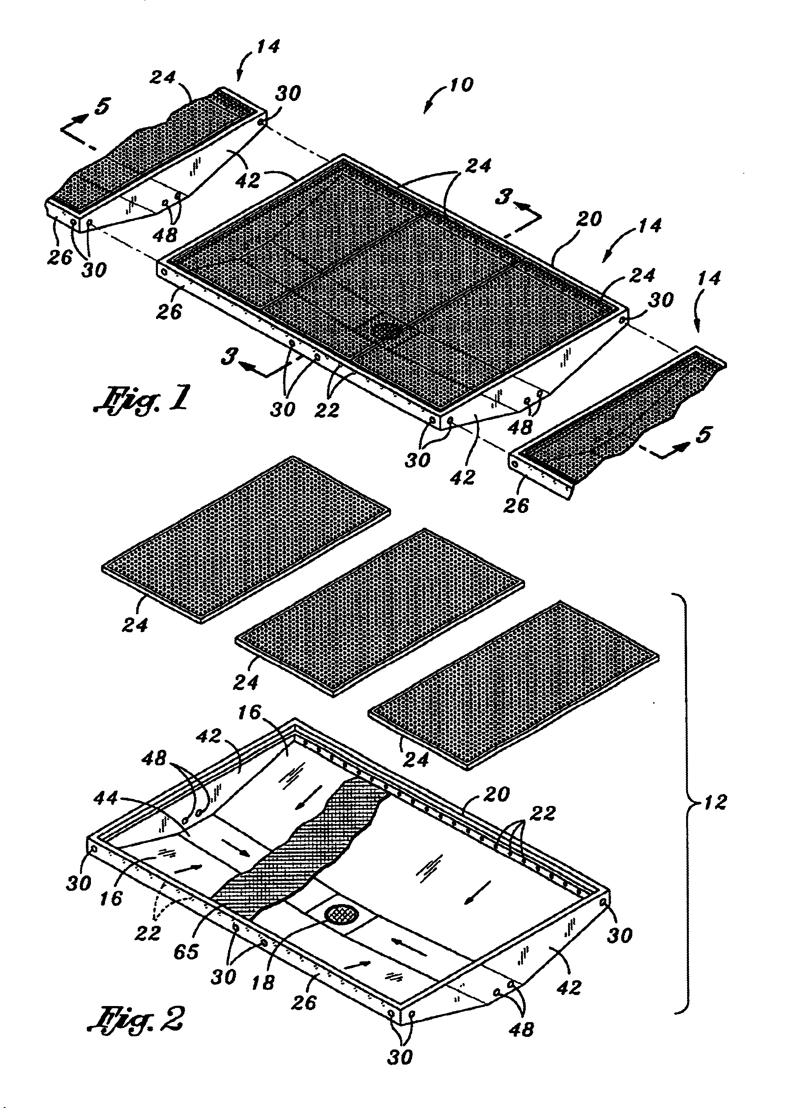
[0020]The present invention will now be described in particular with reference to the accompanying drawings. FIGS. 1 and 2 show a module 12 of a first preferred embodiment of a flooring system 10 for catching waste products of the present invention. FIG. 1 is a perspective view of the first preferred embodiment of the flooring system 10 illustrating the connective relationship of horizontally adjacent modules 12 that make up the flooring system 10. FIG. 2 is an exploded perspective view of the flooring system 10 of FIG. 1 illustrating the module 12 and the relationship of a drain pan 14 and floor grids 24 that make up the module 12 of the first preferred embodiment. Although FIGS. 1 and 2 show the module 12 as having three floor grids 24 disposed upon the drain pan 14, it is contemplated that the module 12 may include at least one floor grid 24 covering the drain pan 14. The drain pan 14 is shown as having a rectangular shape although the drain pan 14 may be configured in a number o...


PUM


Abstract

A self-cleaning flooring system for catching waste products has at least one module comprising a drain pan and a floor grid. The drain pan has a ramp and a central drain outlet. The ramp extends around the drain pan defining a drain pan periphery. The ramp slopes downward from the drain pan periphery towards the drain outlet. The drain pan periphery has a plurality of discharge ports spaced therealong for discharge of flushing fluid onto the ramp such that the waste products are washed down the ramp towards the drain outlet. The floor grid extends across the drain pan and is mounted upon the drain pan periphery for supporting personnel standing thereon while permitting waste products to pass therethrough. The module is interconnectable to horizontally adjacent modules to form the flooring system.

Description

CROSS-REFERENCE TO RELATED APPLICATIONS[0001](Not Applicable)STATEMENT RE: FEDERALLY SPONSORED RESEARCH / DEVELOPMENT[0002](Not Applicable)BACKGROUND OF THE INVENTION[0003]The present invention relates generally to flooring protection and, more particularly, to a self-cleaning flooring system having modules which are interconnectable to horizontally adjacent modules to form a continuous flooring system for catching waste products in a food preparation facility.[0004]In the food preparation industry, sanitation and cleanliness is a major concern. The kitchen flooring in restaurants, hotels, institutions, and commercial food vending facilities in general is subject to frequent spillage from waste products. Such waste products may be in the form of spilled liquids, semi-solids, and small solids and may include grease, oil, water, and an infinite variety of food products. Spilled waste products may create a sanitation hazard as a hot kitchen is a natural breeding ground for harmful bacter...

Claims


Application Information

Patent Timeline
Patent Type & Authority Patents(United States)
IPC IPC(8): A01K1/015E04F19/10E04F19/00E04F17/00A01K1/01
CPCA01K1/0103A01K1/0151E04F17/00E04F19/10Y10T137/87571Y10T137/5762Y10T137/8593
Inventor MACLEAN, JAMES G.CHRISTIAN, DAVID L.LONG, JR., DARELL J.
Owner DTS ENTERPRISES INC
Why Eureka
Try Eureka