Method, apparatus and system for sensing air borne hazardous materials

a hazardous material and air technology, applied in the field of chemical, biological, radioactivity and air pollution detectors, can solve the problems of cumbersome, bulky, difficult to rapidly deploy, and not intended for continuous measuremen

Active Publication Date: 2005-09-13
AEROMECHANICAL SERVICES
View PDF19 Cites 29 Cited by
  • Summary
  • Abstract
  • Description
  • Claims
  • Application Information

AI Technical Summary

Problems solved by technology

Hand-held gas chromatography, spectral analyzers, and Geiger counters are intended for spot measurement and are generally cumbersome, bulky, and traditionally complex and hard to rapidly deploy.
Additionally, they are not intended for continual measurements except in a localized area.
Biological testing using cultures does not provide immediate results.
Generally, hazardous agent testing is limited to a single measurement and requires the tester to maintain a physical proximity to the potential hazard.
Geiger counters and other radioactivity detection means do not provide assessment of the distribution of hazardous agents throughout the atmosphere at a range of altitudes and geographic locations.
These approaches also require suspicion that such a potential threat exists.
In each measurement approach difficulties and inaccuracies are introduced into the determination of a potential hazard by manual handling of the test.
Additionally, other atmospheric factors such as winds aloft and convective activity that could potentially influence the spread of such a contaminant are not integrated into any of the above mentioned testing outputs.
As such, the sensing and predicted path of a potential hazardous agent is not possible or is very difficult and limited under current approaches.
Present methods of hazardous agent detection do not provide assessment of the distribution and dispersion of hazardous agents throughout the atmosphere at a range of altitudes and geographic locations.

Method used


Image

  • Method, apparatus and system for sensing air borne hazardous materials
  • Method, apparatus and system for sensing air borne hazardous materials
  • Method, apparatus and system for sensing air borne hazardous materials

Examples


Embodiment Construction

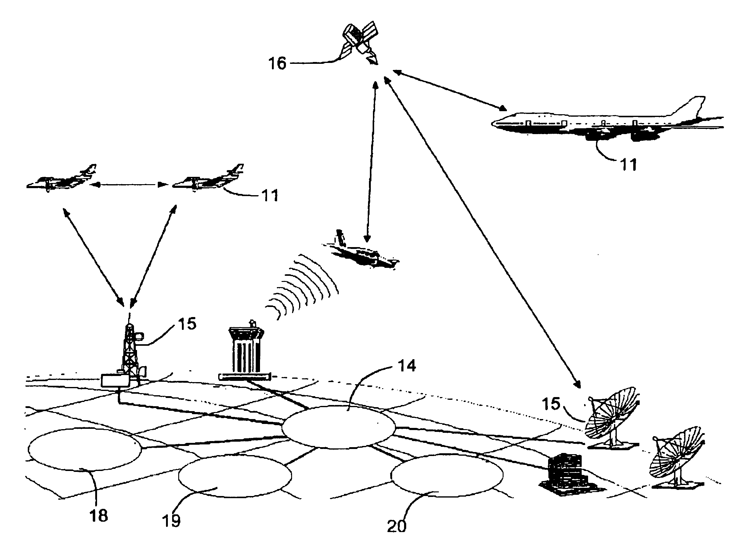
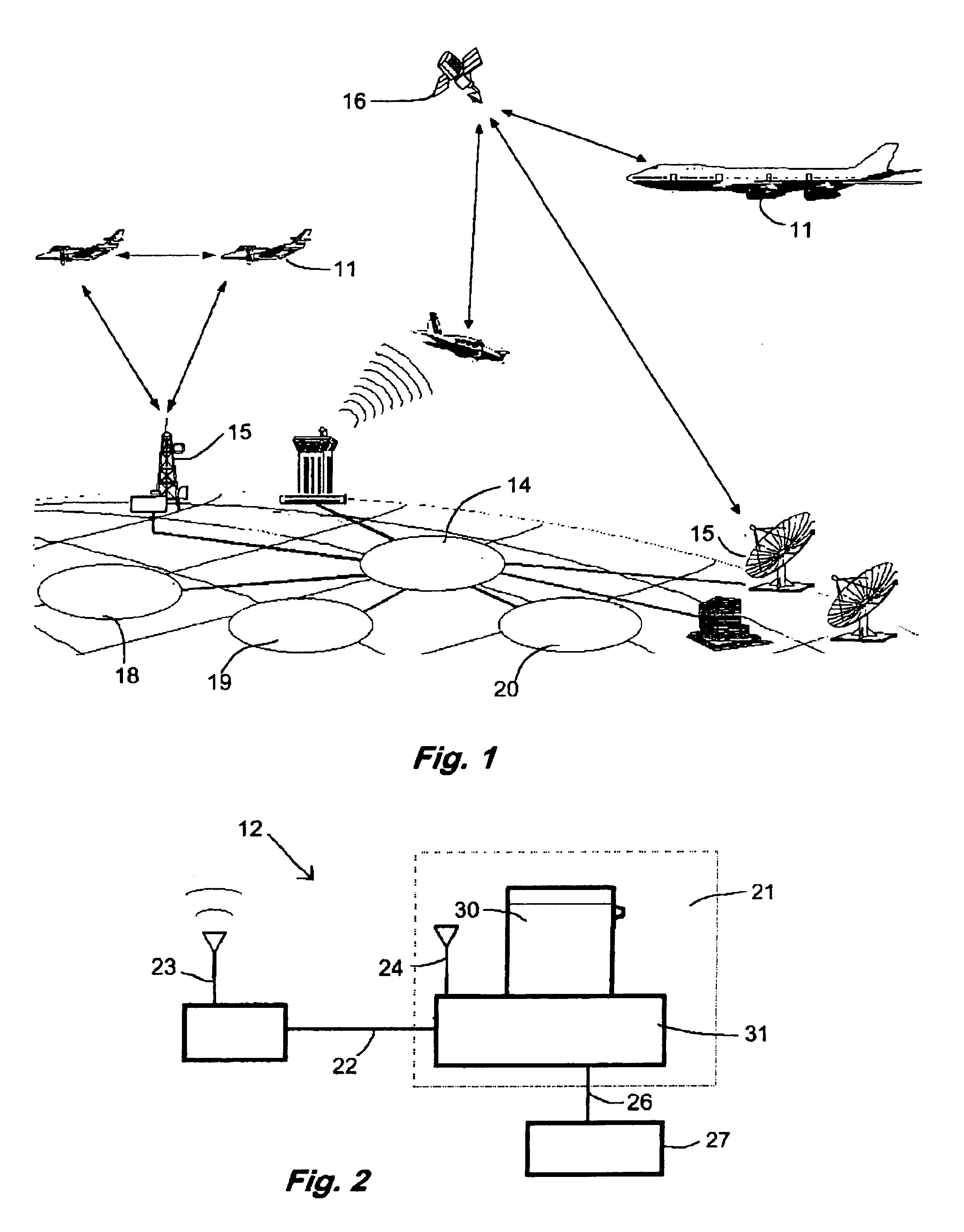
[0015]Referring now to FIGS. 1 and 2, a system embodying features of the present invention includes aircraft 11 equipped with hazardous material sensing apparatus 12, and a ground network 14. The ground network 14 includes communications towers 15, for receiving data from the sensing apparatus 12, linked to computers that store and analyze the data. Preferably the aircraft 11 and ground network 14 are linked through communications satellites 16. The ground network 14 may further include links to government agencies such as the National Weather Service 18, the NOAA / Meteorological Modeling Labs 19 or a DOD Analysis Facility 20.

[0016]The sensing apparatus 12, as shown in FIG. 2 has a GPS unit 24 and a sensor 21, linked by a first data line 22 to a transceiver 23 and by a second data line 26 to a heading module 27. The sensor 21 provides an ASCII or binary output via the first data line 22 directly to the transceiver. The GPS unit 24 provides time, position and altitude tagging of the d...


PUM

PropertyMeasurementUnit
shapeaaaaaaaaaa
temperatureaaaaaaaaaa
humidityaaaaaaaaaa

Abstract

Apparatus for detecting hazardous materials is mounted on an aircraft and has a sensor, a heading unit, a transceiver and a GPS unit. The sensor has an airfoil shaped probe and an electronics module. The probe has a positive airflow, enclosed sensing chamber with a hazardous material sensing element. The system for detecting hazardous materials includes aircraft with the hazardous material detecting apparatus and a ground network. The method for detecting hazardous materials includes the steps of providing aircraft with hazardous material sensing apparatus and a ground network, collecting hazardous material and atmospheric data with the sensing apparatus, transmitting the position, wind velocity and hazardous material data to the ground network, calculating distribution of hazardous materials in the atmosphere, generating a real-time map of distribution of hazardous materials and predicting dispersion of the hazardous materials in the atmosphere.

Description

[0001]This application claims the benefit under 35 U.S.C. § 119(e) of the U.S. provisional patent application No. 60 / 422,790 filed Oct. 31, 2002.TECHNICAL FIELD[0002]The present invention relates to chemical, biological, radioactivity and air pollutant detectors and more particularly to a method, apparatus and system for rapidly measuring the presence, distribution, and dispersion of hazardous materials in the atmosphere.BACKGROUND ART[0003]Prior known sensors and systems used for sensing hazardous agents include hand-held gas chromatography “sniffing” devices, spectral analyzers, biological testing cultures, live animal exposures, and Geiger counters. Hand-held gas chromatography, spectral analyzers, and Geiger counters are intended for spot measurement and are generally cumbersome, bulky, and traditionally complex and hard to rapidly deploy. Additionally, they are not intended for continual measurements except in a localized area. They also are typically stand-alone and do not inc...

Claims


Application Information

Patent Timeline
Patent Type & Authority Patents(United States)
IPC IPC(8): G01N1/26G01N33/00G01N1/22
CPCG01N1/26G01N33/0075G01N1/2273G01N2001/021G01N2001/2279G01N2001/2285
Inventor BURNS, JOSEPH DANDERSON, MARK V
Owner AEROMECHANICAL SERVICES
Why Eureka
Try Eureka