Hydraulic lash adjuster and improved method of assembly thereof

a technology of lash adjuster and lash extension, which is applied in the direction of valve arrangement, machine/engine, metal-working apparatus, etc., can solve the problems of non-standard hla, long lead time to produce the required hla, and waste of material,

Inactive Publication Date: 2005-09-13
EATON CORP
View PDF4 Cites 10 Cited by
  • Summary
  • Abstract
  • Description
  • Claims
  • Application Information

AI Technical Summary

Benefits of technology

[0009]Accordingly, it is an object of the present invention to provide an improved hydraulic lash adjuster, and an improved method for assembling such a lash adjuster, which makes it possible to verify the proper performance of the check valve assembly prior to assembly of the entire HLA.
[0010]It is another object of the present invention to provide an improved HLA, and an improved method of assembly thereof, in which the performance of the check valve assembly and the leakdown performance each may be changed, independently of the other, without designing and tooling an entirely new HLA.
[0011]It is another, related object of the present invention to provide an improved HLA, and a method of assembly thereof, which greatly facilitates the design and production of an HLA which varies, in perhaps only one aspect or performance criteria, from a standard HLA model already designed and tooled and, possibly in production.

Problems solved by technology

Unfortunately, it occurs periodically that after the HLA is completely assembled, performance testing of the HLA shows that, either the leakdown performance or the check valve assembly performance is not within the specified, permissible limits.
When such unacceptable performance occurs, the entire HLA is then either scrapped, (thus wasting several parts of the HLA which, individually, may have been acceptable parts, and therefore, wasting the material, labor and machining costs associated with those parts), or the HLA is sent through some sort of rework process, wherein parts are disassembled, re-inspected, re-sized, and re-assembled.
Such a rework process is not only time-consuming, but is also quite expensive.
This approach to designing and manufacturing new HLA models adds substantially to the overall cost of manufacture of the HLA and the lead time to produce the required, non-standard HLA.

Method used


Image

  • Hydraulic lash adjuster and improved method of assembly thereof
  • Hydraulic lash adjuster and improved method of assembly thereof
  • Hydraulic lash adjuster and improved method of assembly thereof

Examples


Embodiment Construction

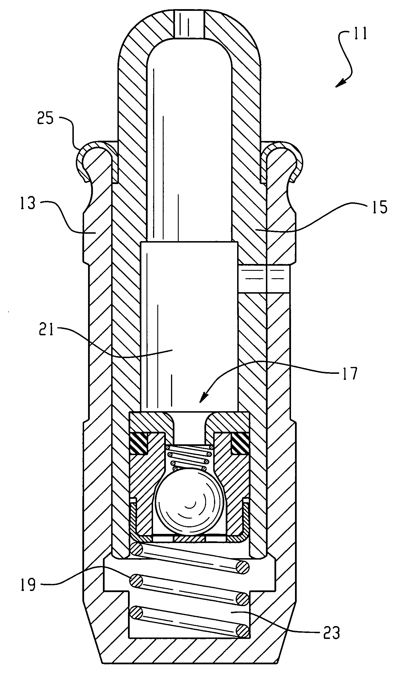
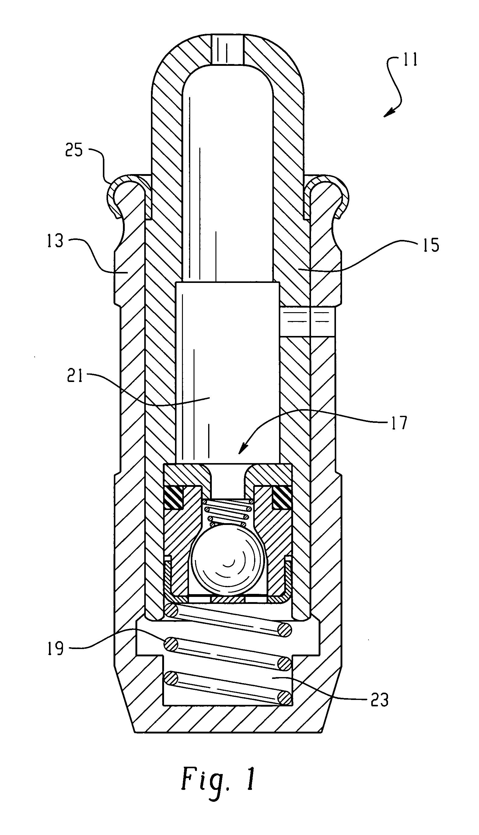
[0023]Referring now to the drawings, which are not intended to limit the invention, FIG. 1 is an axial cross-section of one particular embodiment of HLA, by way of example only, made in accordance with the present invention. Therefore, FIG. 1 shows an hydraulic lash adjuster, generally designated 11, which may be of the general type illustrated and described in U.S. Pat. No. 5,855,191, assigned to the assignee of the present invention and incorporated herein by reference. However, those skilled in the art will understand that the present invention, in each of its aspects, is not limited to the particular type of or configuration of HLA shown in FIG. 1, as will be explained in greater detail subsequently.

[0024]The HLA 11, as shown in FIG. 1, may be of a general type and configuration well known to those skilled in the art (except where noted otherwise hereinafter), and will be described only briefly at this point. The HLA 11 includes a body 13 which, as noted previously, would typica...


PUM

PropertyMeasurementUnit
pressureaaaaaaaaaa
outer diameteraaaaaaaaaa
inner diameteraaaaaaaaaa

Abstract

A hydraulic lash adjuster (11) for an internal combustion engine, and an improved method of assembly of such a lash adjuster. The lash adjuster (11) is of the type having a body (13), a plunger (15), and a check valve assembly (17). In accordance with one aspect of the invention, the check valve assembly comprises a cartridge (17A;17B) comprising a member (27;41) separate from the plunger (15) and defining a valve seat (27S;41S). The check valve cartridge is capable of being assembled and tested for compliance with a predetermined relationship of flow versus pressure differential, prior to assembly into the plunger (15). In accordance with the improved method of assembly, a plurality of different bodies (13A;13B) and plungers (15A;15B;15C;15D) is provided, as well as a plurality of different, interchangeable check valve cartridges (17A;17B), and the assembly operator selects a body, a plunger, and a cartridge to provide an assembled lash adjuster having the predetermined, desired operating parameters.

Description

BACKGROUND OF THE DISCLOSURE[0001]The present invention relates to hydraulic lash adjusters for internal combustion engines, and more particularly, to an improved check valve assembly for use in such lash adjusters, and to an improved method of assembling such lash adjusters.[0002]In a conventional hydraulic lash adjuster (HLA) of the type to which the present invention relates, there is an outer body, which is typically disposed within a mating bore in the engine cylinder head, and disposed within the body is an output plunger assembly engaging a rocker arm. The output plunger assembly may be of either a one-piece or a two-piece construction, and typically, includes a ball plunger element which engages a socket formed in an “underside” surface of the rocker arm. A blind bore formed within the body cooperates with the plunger assembly to define a high pressure chamber, as is well known to those skilled in the art. There is normally a biasing spring seated within the high pressure ch...

Claims


Application Information

Patent Timeline
Patent Type & Authority Patents(United States)
IPC IPC(8): F01L1/24
CPCF01L1/2405F01L1/2422Y10T29/49247Y10T74/2107F01L1/20F01L1/24
Inventor MASELLO, JOSE F.CECUR, MAJO
Owner EATON CORP
Why Eureka
Try Eureka