
Conveyor system and method for transferring stacks of paper or the like to a discharge conveyor

a conveyor and paper stack technology, applied in conveyors, furnace components, light and heating equipment, etc., can solve the problems of relative shortness, achieve the effect of improving the conveyor system, avoiding dead times, and great flexibility of operation

Inactive Publication Date: 2005-09-13
BIELOMATIK LEUZE GMBH & CO
View PDF8 Cites 14 Cited by
  • Summary
  • Abstract
  • Description
  • Claims
  • Application Information

AI Technical Summary

Benefits of technology

[0005]The object of the invention is to further improve the conveyor system and the method according to EP 465 916 B and in particular in the case of great flexibility of operation to avoid dead times resulting from transfer, there by ensuring a troublefree transfer sequence, even at high operating speeds.SUMMARY OF THE INVENTION
[0006]This object is achieved by a conveyor system in which with each stacking position is associated a gripper pair of two grippers which are movable independently of one another and which are operable for gripping or releasing the stack. This makes it possible for in each case one of the grippers of the pair to be moved into a position in which it can grip or seize the next stack, whilst the other gripper of the pair is still in engagement with the preceding stack, positions same over the discharge conveyor section and finally releases it. Therefore due to the fact that in each case one gripper of the pair is already performing the return movement when the other is still pulling or positioning a stack row, for transferring from the stacking position to the discharge conveyor sections is available virtually all the time required for stack formation or the stack supply. This can be relatively short time, because as a result of high operating speeds and the fact that working takes place in multilayer manner, small format cross-cutters can produce numerous stacks every minute.

Problems solved by technology

This can be relatively short time, because as a result of high operating speeds and the fact that working takes place in multilayer manner, small format cross-cutters can produce numerous stacks every minute.

Method used


Image

  • Conveyor system and method for transferring stacks of paper or the like to a discharge conveyor
  • Conveyor system and method for transferring stacks of paper or the like to a discharge conveyor
  • Conveyor system and method for transferring stacks of paper or the like to a discharge conveyor

Examples


Embodiment Construction

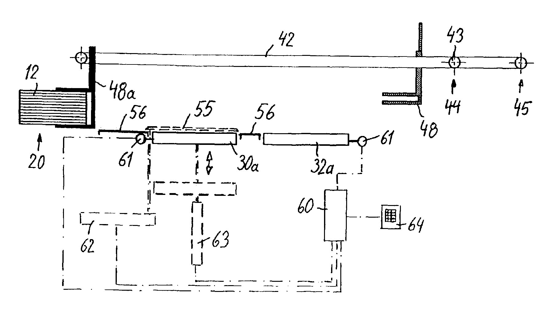
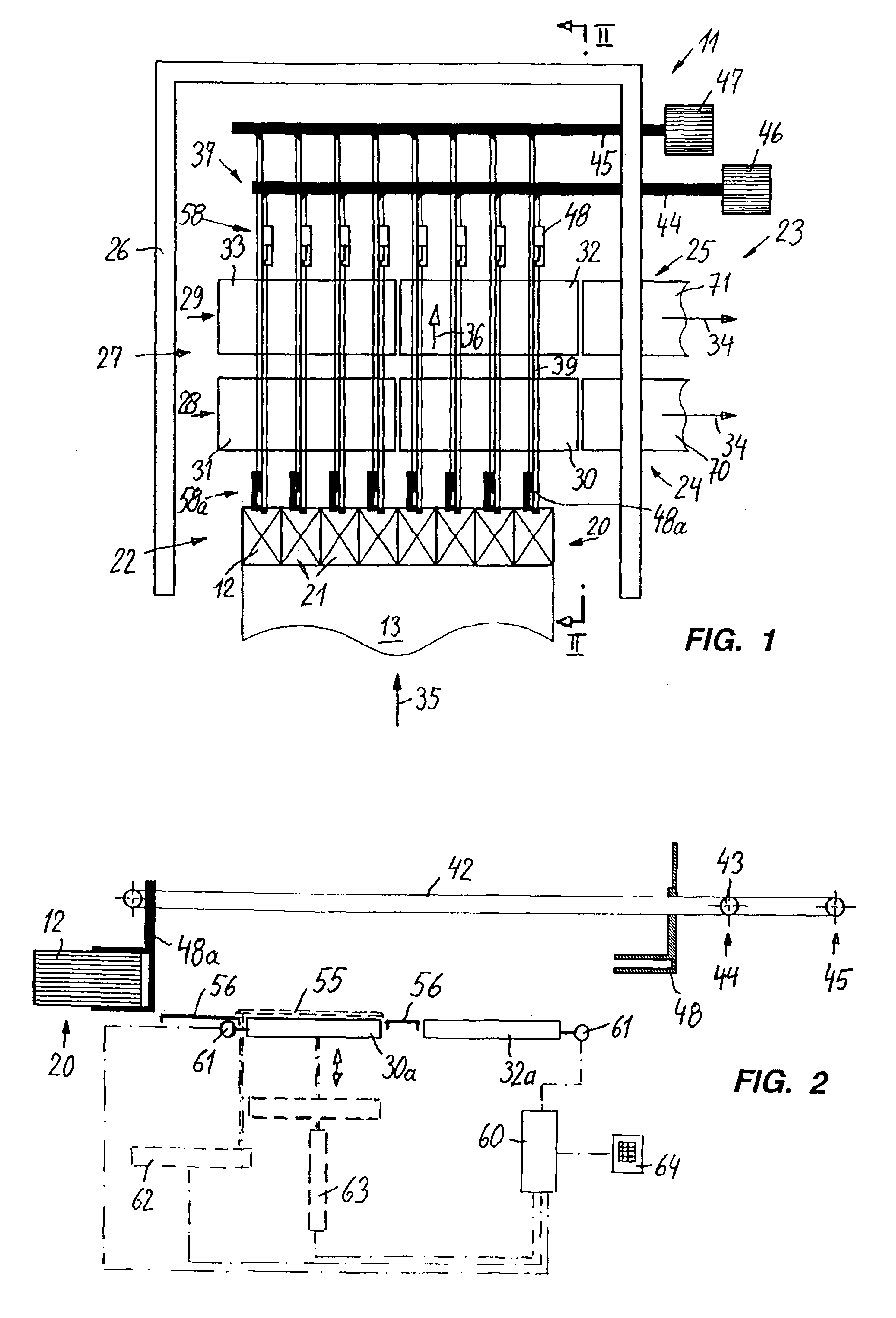
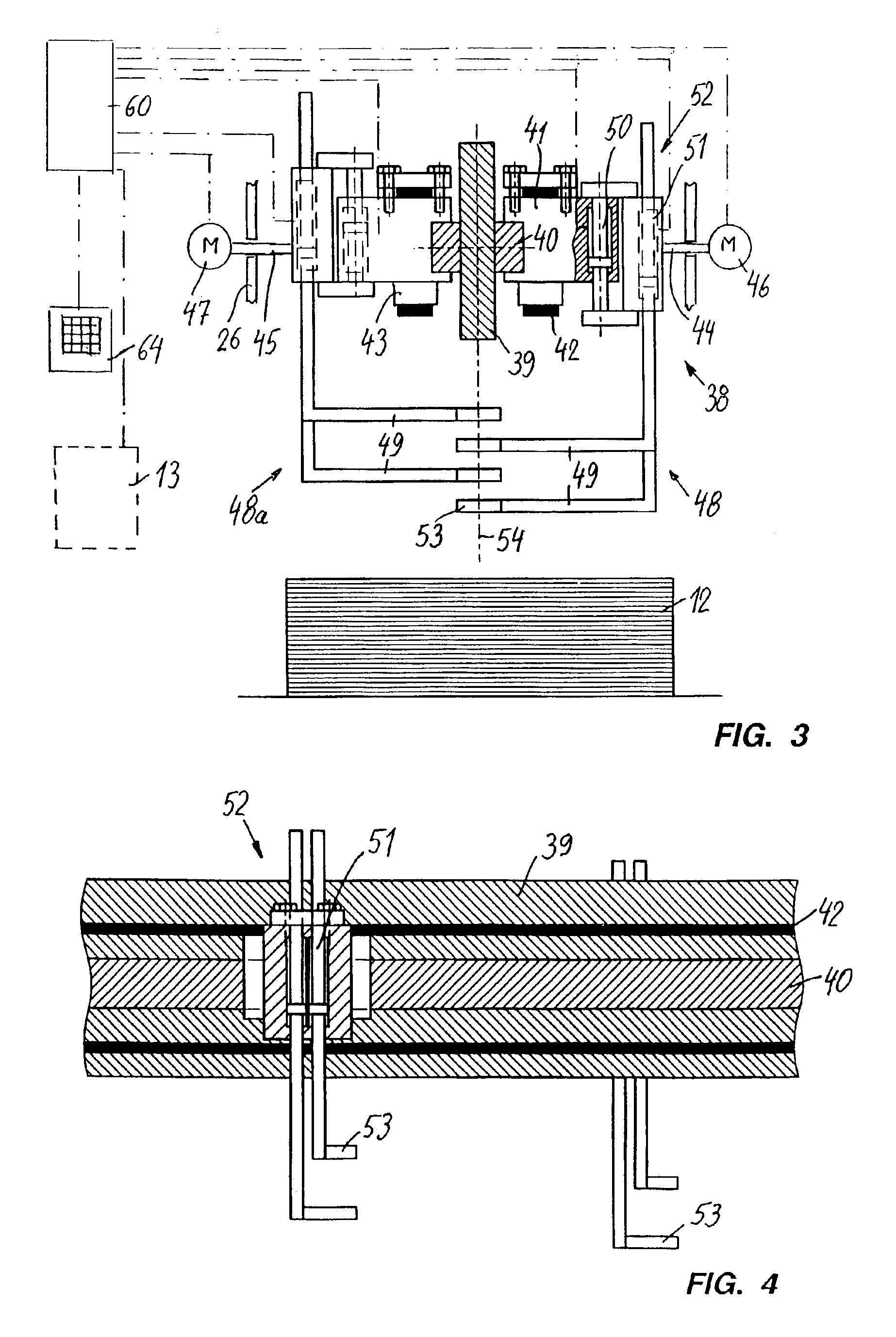
[0021]FIGS. 1 to 10 show in a highly diagrammatic representation form a conveyor system 11 for stacks 12 formed from sheet layers.

[0022]The conveyor system 11 is positioned close to the end of a paper converting machine 13 shown in FIG. 16. In the embodiment it is a matter of a small format cross-cutter containing pull-off rolls 14 for five paper webs 15, which in each case come from a large paper reel 16 and which are jointly worked in superimposed manner. A slitter 17 slits the paper webs 15 in waste-free manner into format-maintaining longitudinal strips, which are then cut with a cross-cutter 18 to the corresponding format and are transferred into further stations 19 in a scaled sheet flow, checked, separated through the discharge of faulty sheets and finally collected in a stacking station 20 to sheet stacks of the desired height (e.g. 500 sheets). Corresponding to the number of blanks, i.e. juxtaposed stacks cut from a paper web width, numerous stacks 12 are formed in the stac...


PUM

PropertyMeasurementUnit
anglesaaaaaaaaaa
flexibilityaaaaaaaaaa
timeaaaaaaaaaa

Abstract

The conveyor system (11) is used for transferring rows or large cycles (66) of sheet stacks (12) from the stacking station (20) of a paper converting machine, e.g. a small format cross-cutter to several parallel-running discharge conveyor belts (24, 25). For this purpose grippers or tongs (48) are provided, which are guided on gripper supports (39) and which can draw the stacks (12) from stacking station (20) via conveyor belts (24, 25). For each stacking position (21) there are two grippers (48, 48a), which in each case alternatively grip and transfer a stack, whilst the other gripper performs the return movement and passes into its waiting position upstream of the stacking station.

Description

BACKGROUND OF THE INVENTION[0001]The invention relates to a conveyor system for stacks of paper or the like formed from sheet layers and a method for transferring such stacks between a supply station and a discharge conveyor.[0002]EP 465 916 B describes such a conveyor system and a method. It is used in installations where stacks of flat materials are juxtaposed in rows, e.g. in so-called small format cross-cutters, which produce from paper webs stacks of use format sheets, e.g. copy paper packs. The stacks arriving in juxtaposed manner in a row are transferred in the conveyor system to discharge conveyors, which run at right angles to the supply direction to the machine. The individual rows are connected to one another therein, so that the individual stacks can be separated to a predetermined spacing and in this way generally pass to packing machines.[0003]EP 465 916 B describes an installation having in a discharge station two substantially parallel discharge conveyor sections on ...

Claims


Application Information

Patent Timeline
Patent Type & Authority Patents(United States)
IPC IPC(8): B65H31/30B65G47/82B65G47/90B65G47/86B65H31/32
CPCB65G47/901B65G47/907B65H31/3045B65H2301/42242B65H2403/55B65H2701/1822B65H2220/09
Inventor MEYER, AXEL
Owner BIELOMATIK LEUZE GMBH & CO
Learn More