Threaded connection engagement and disengagement system and method

a technology of connecting system and disengagement system, applied in the field of systems and methods, can solve the problems of fatigue life failure, early fracture or other failure of the connection, and introduce relative displacement between parts that tend to grow, so as to improve the operating life, facilitate and reliable disengagement, and simple procedure

Inactive Publication Date: 2005-09-13
CARTSENSEN KENNETH J
View PDF9 Cites 20 Cited by
  • Summary
  • Abstract
  • Description
  • Claims
  • Application Information

AI Technical Summary

Benefits of technology

[0012]This arrangement permits convenient and reliable disengagement of each of a succession of sucker rod-coupling connections by a simple procedure. With the gripper arms for the coupling retracted, the coupling at the end of a sucker rod is simply placed in position against a fixed reference gripper head at the lowermost position and the other two gripper heads are closed in against it with selected forces determined by the hydraulic pressure limit. The torque wrench is moved into position on the wrench flat by pivoting the hydraulic unit slightly, and the wrench drive arm is drawn through a selected angle, which need not be greater than 30° in most instances, but which can be taken through a 90° angle to assure that the coupling can thereafter be manually removed.
[0013]The same mechanism is useful for precision make up of one sucker rod and a coupling. In the new sucker rod coupling systems of the Carstensen application, relationships are utilized in which the first sucker rod that is inserted is threaded in to a selected displacement beyond hand tight contact between the shoulder and coupling end. In that position it serves as a reference for the opposing end of the second sucker rod either through an intervening torque washer or directly. When both are engaged properly, they have like prestresses that substantially improve operating life. To this end, the coupling is placed at the gripping position as previously described, with the attached sucker rod, which has been threaded to tightness at the hand tight position, extending outwardly. The wrench arm is started from a position such as to permit the clockwise direction of rotation that is needed for tightening. The sucker rod is driven through a selected arc, such as one quarter turn, to effect the desired positional engagement and prestressing. Alternatively, applied torque can be determined by setting the hydraulic pressure limit of the actuator.

Problems solved by technology

These analyses have shown that, with repeated cycling, minor physical imperfections in a coupling or adjacent rod segment tend to become stress riser points, and that the imperfections grow with time, leading to early fracture or other failure of the connection.
Relative movement between the rod pin end and the coupling, as can arise with excessive or inadequate prestressing at the threaded and shoulder regions, also introduces relative displacements between parts that tend to grow with time.
This is another frequent cause of fatigue life failures.
Particular care is paid by operators to the steps of disengagement of sucker rods from couplings, but there are other inherent problems which have not heretofore been satisfactorily overcome.
This of course leaves the coupling still engaged to the other sucker rod, and this connection cannot be broken, usually, without applying several thousand foot pounds of torque to the connection.
A smooth-faced friction wrench will typically not provide enough manual retention force without slipping, so that sand is often interposed between the coupling and wrench faces to increase frictional restraint, which is not always adequate and also may mark the coupling surface.
As pointed out in Clark U.S. Pat. No. 5,010,635, this manual procedure is time consuming and often dangerous, so Clark proposes a mechanical, power operated friction wrench design.
This mechanical and presumably automatic machine has not found widespread use, however, because of various difficulties encountered in practice, because of a lack of versatility in accepting different sucker rod sizes, and because it is not intended for use in precision make up, but only in breaking connections.
Crews will often start with the circumferential displacement method and observe readings of how much torque is required, and thereafter follow the pressure or torque indicators instead of trying to match the displacement lines precisely, which is much more time consuming.
Extensive studies of pin end to coupling engagement, however, have shown that these prior techniques are subject to substantial variations in final relative positions, depending upon such factors as the relative wear of the thread forming tool, and the number of uses of the coupling or pin.
Even though the elements are within tolerances, the actual engagement that results varies to an undesirable extent.

Method used


Image

  • Threaded connection engagement and disengagement system and method
  • Threaded connection engagement and disengagement system and method
  • Threaded connection engagement and disengagement system and method

Examples


Embodiment Construction

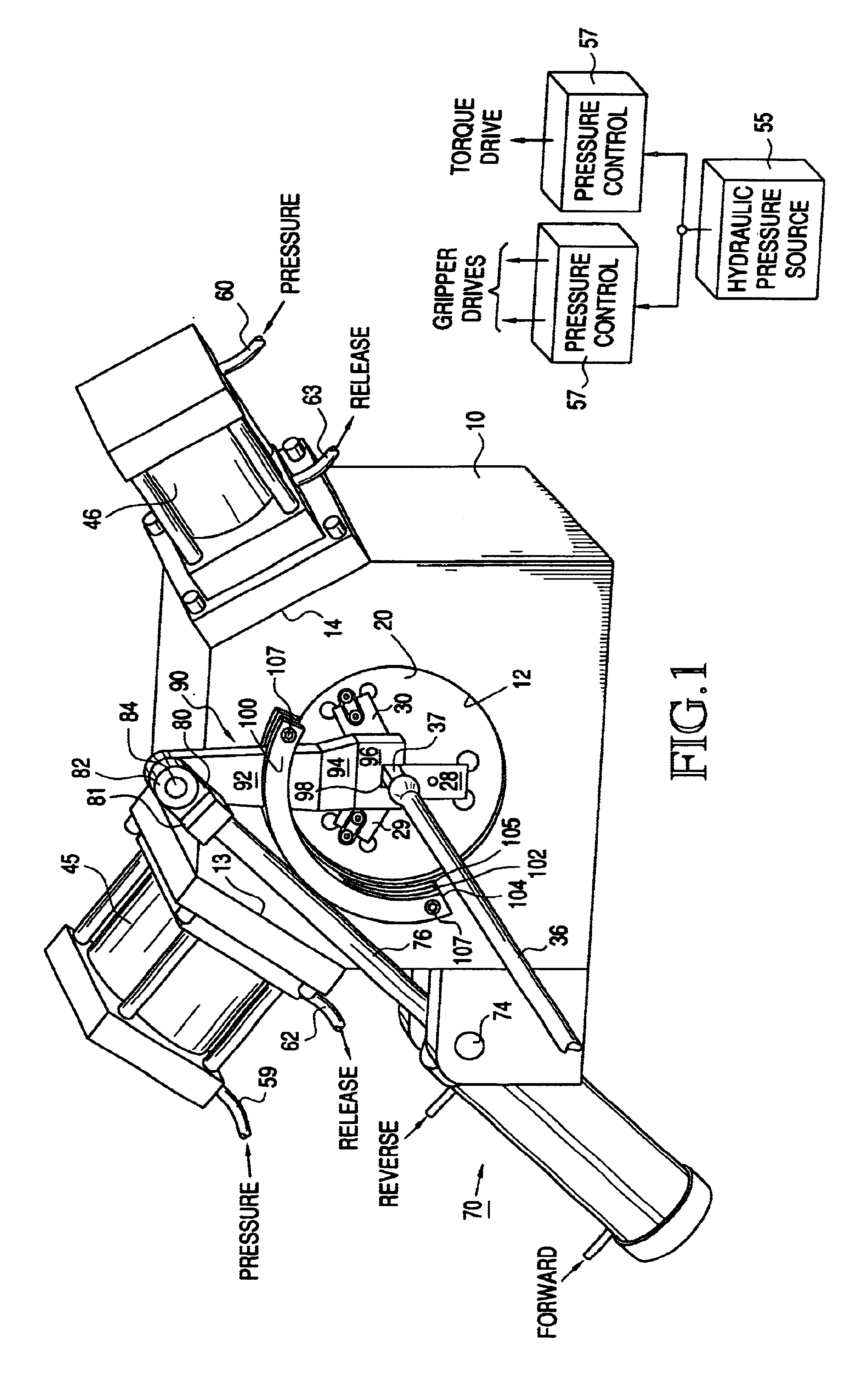
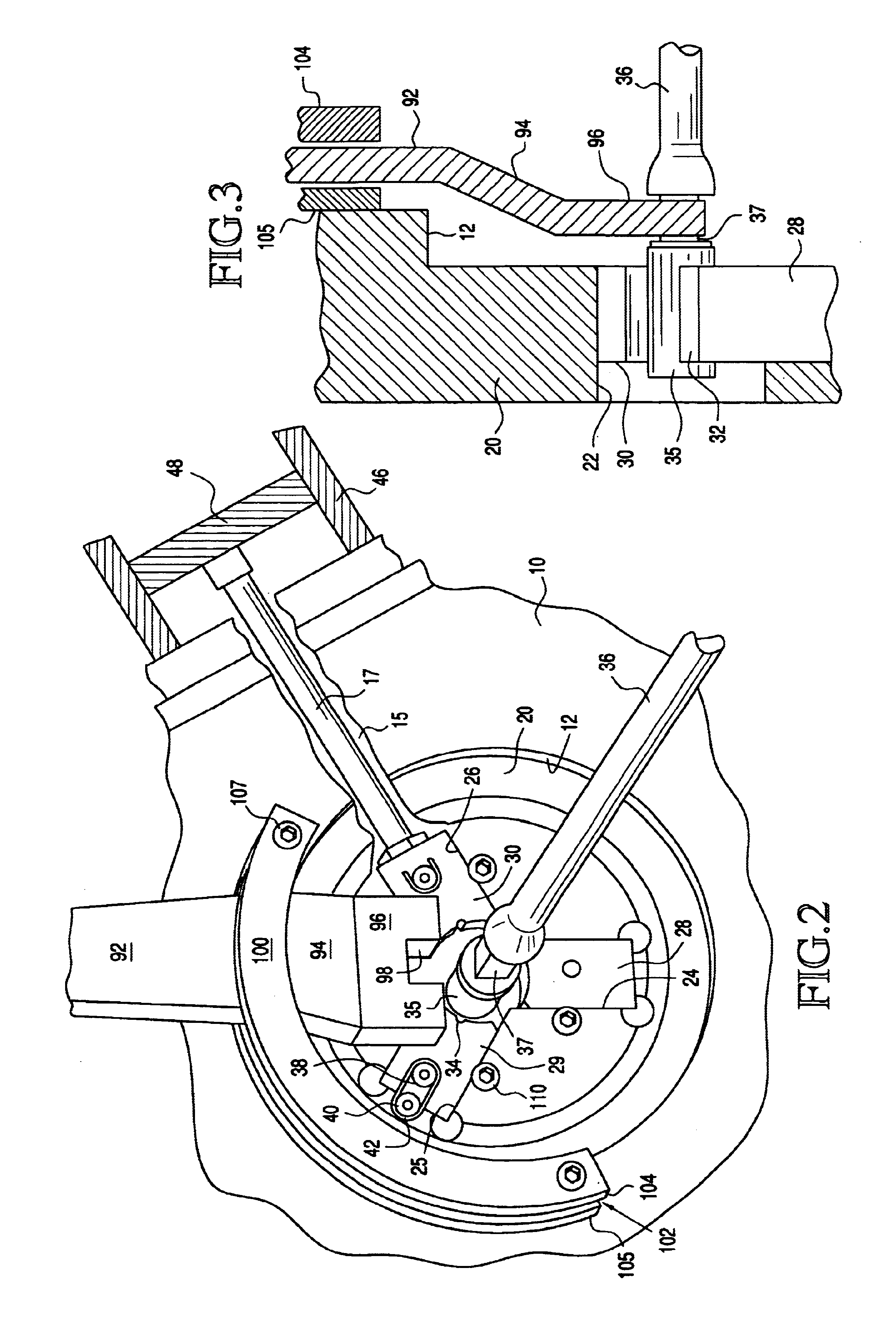
[0026]A system in accordance with the invention, referring now to FIGS. 1-4, is structured on a massive and integral base block 10, typically of steel, and therefore adequate to withstand the high forces that are generated in operation. The base block 10 includes, in one wall, a central recess 12 which is concentric with the central axis of the coupling and sucker rod combination that is to be engaged or disengaged. The two top corners 13, 14 of the generally rectangular base block 10 are oppositely angled and include interior bores 15 (FIG. 2) within which drive elements 17 are radially positioned relative to the central axis. Within the central recess 12, a reference plate 20 for gripper elements is mounted transverse to the central axis and itself includes a central bore 22 along the central axis and concentric therewith. The reference plate 20 is of sufficient thickness to withstand high stresses and the central bore 22 is of adequate diameter to receive any sucker rod coupling ...


PUM

PropertyMeasurementUnit
angleaaaaaaaaaa
angleaaaaaaaaaa
outer diametersaaaaaaaaaa

Abstract

A system for making and breaking connections between the pin ends of sucker rods and coupling sleeves employs a hydraulically powered system of radially driven gripper heads which are interchangeable to accept different sucker rod sizes. A torqueing system adjacent the gripper head system is also hydraulically driven, employing a pivotally coupled free end on a torque wrench which engages the wrench flat on the sucker rod at its opposite end. The coupling is securely retained without marring the coupling surface while the torque necessary to make or break the connection is applied rapidly and controllably. The system can also be used to advantage in preassemble sucker rods into couplings with precise prestress, using an improved connection design. A sucker rod string can then be assembled readily in the field with invariant optimum prestress conditions at each connection.

Description

REFERENCE TO PRIOR ART[0001]This application relies for priority on provisional application Ser. No. 60 / 354,880 filed Feb. 5, 2002. This invention also is a continuation-in-part of application Ser. No. 09 / 961,391 filed Sep. 25, 2001 by Kenneth J. Carstensen and entitled “Connectable Rod System for Driving Downhole Pumps for Field Installations”.FIELD OF THE INVENTION[0002]This invention relates to systems and methods for handling threaded connections between rods and tubular goods, and particularly to making and breaking connections for sucker rods that are employed in petroleum production.BACKGROUND OF THE INVENTION[0003]When manipulating rods and tubular goods, particularly in the petroleum industry, it is often required to disengage or “break” connections between successive lengths of rod or tubing, and to meet specific operating requirements when doing so. In other circumstances, the same threaded interconnections have to be engaged or “made up” very precisely.[0004]Specific exa...

Claims


Application Information

Patent Timeline
Patent Type & Authority Patents(United States)
IPC IPC(8): E21B17/042E21B17/02F16B37/14F16B37/00F16B7/18
CPCE21B17/0426F16B7/182F16B37/145Y10T29/49821Y10T403/27Y10T403/32909Y10T29/49874Y10T29/53687Y10T29/49881Y10T403/457
Inventor CARTSENSEN, KENNETH J.
Owner CARTSENSEN KENNETH J
Why Eureka
Try Eureka