Optical device for intraocular observation
an optical device and intraocular observation technology, applied in the field of optical devices, can solve the problems of inability to properly classify glaucoma, inability to easily sterilize, and limited scope of observation, and achieve the effects of simple construction, low cost of manufacture, and versatile application
- Summary
- Abstract
- Description
- Claims
- Application Information
AI Technical Summary
Benefits of technology
Problems solved by technology
Method used
Image
Examples
first embodiment
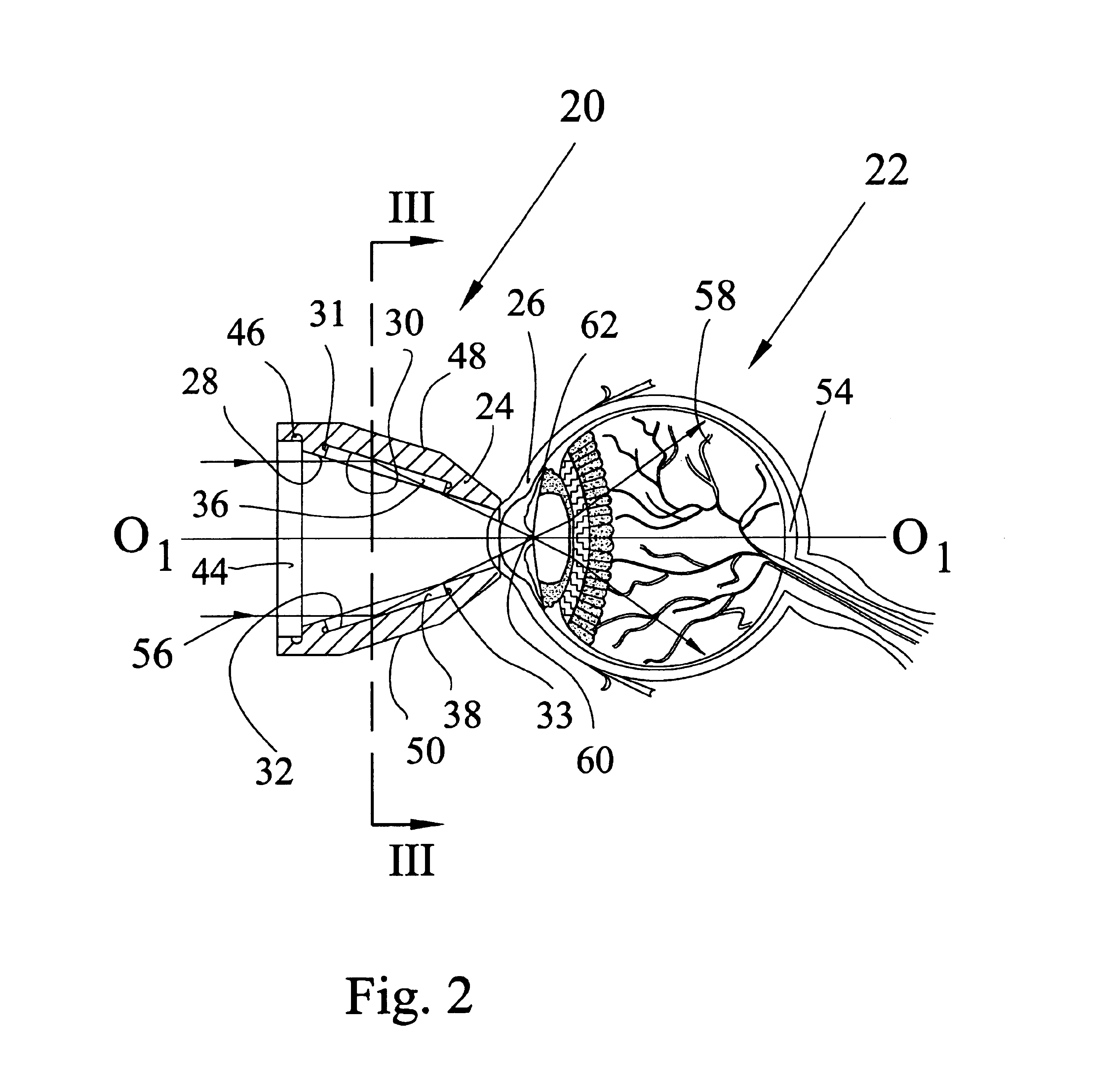
[0048]FIG. 2 is a longitudinal sectional view of a reusable gonioscope 20 made in accordance with the invention. The gonioscope 20 is shown in a working position on a patient's eye 22 with a central optical axis O1-O1 of the gonioscope coinciding with the central axis of the eye. The gonioscope 20 has a hollow tapered body 24 molded from a biocompatible plastic which is allowed for contact with the cornea 26 of the eye. Examples of such plastics are the following: polycarbonate, acrylic, or the like.
[0049]FIG. 3 is a cross-sectional view of the gonioscope 20 along the line III—III of FIG. 2. The inner surface 28 of the body 24 has at least one, but preferably a plurality of recesses 31, 33, 35. In FIG. 2 the diametrical arrangement of the recesses 31 and 33 is shown conventionally. It is understood that three recesses are shown as an example and that their number may be less or greater than three. The recesses 31, 33, 35 accommodate reflection mirror inserts 36, 38, 40, respectively...
second embodiment
[0055]FIG. 5 illustrates the invention. FIG. 6A is a view in the direction of arrow A of FIG. 5. In this embodiment, those parts and elements of the gonioscope that are identical to those of the previous embodiment are designated by the same reference numbers with an addition of letter “a”. A gonioscope 20a comprises a tapered body 24a with flats 30a and 32a formed on the inner surface 28a of the tapered body 24a. The flats 30a, 32a, and 34a (only 30a and 32a are seen on FIG. 5) may have shallow recesses 31a, 33a, and 35a (only 31a and 33a are sheen on FIG. 5) having the depth equal to the thickness of the glass plate mirrors 36a, 38a, and 40a inserted into the aforementioned recesses 31a, 33a, and 35a (only 36a, 38a are seen on FIG. 5), respectively. The glass plate mirrors can be fixed in the recesses by glue. If necessary, as shown in FIG. 6B which is a fragmental view of one mirror on the inner surface 28a′ of the gonioscope 20a′, the flats, such as the flat 34a′, may be formed ...
PUM
 Abstract
Description
Claims
Application Information
 - R&D
- Intellectual Property
- Life Sciences
- Materials
- Tech Scout
- Unparalleled Data Quality
- Higher Quality Content
- 60% Fewer Hallucinations
Browse by: Latest US Patents, China's latest patents, Technical Efficacy Thesaurus, Application Domain, Technology Topic, Popular Technical Reports.
© 2025 PatSnap. All rights reserved.Legal|Privacy policy|Modern Slavery Act Transparency Statement|Sitemap|About US| Contact US: help@patsnap.com


