Vertical axis wind turbine

a vertical axis, wind turbine technology, applied in the direction of wind motors with perpendicular air flow, non-positive displacement fluid engines, liquid fuel engine components, etc., can solve the problems of omni-directional vawts, hawts that do not lend themselves to do-it-yourself construction and actually grow attractive with size, and negative impact on overall system efficiency and cost. , to achieve the effect of excellent efficiency

Inactive Publication Date: 2005-09-13
OHLMANN HANS ARMIN
View PDF11 Cites 91 Cited by
  • Summary
  • Abstract
  • Description
  • Claims
  • Application Information

AI Technical Summary

Benefits of technology

[0020]It is an object of the invention to provide a vertical axis wind turbine (VAWT) wit

Problems solved by technology

While this type of wind turbine claims the highest efficiency, they are burdened with some substantial disadvantages:a. They are mono-directional, which means they have to be turned into the wind.b. Their minimum operational wind speed (cut-in speed) is relatively high and the maximum wind speed (cut-out speed) they can endure is relatively low, allowing for only a relatively narrow window of operation, beyond which they are prone to damage and have to stop operating.c. Their serviceable components sit high up in the so-called nacelle, on top of a tall pillar, which is inconvenient for service and parts

Method used


Image

  • Vertical axis wind turbine
  • Vertical axis wind turbine
  • Vertical axis wind turbine

Examples


Embodiment Construction

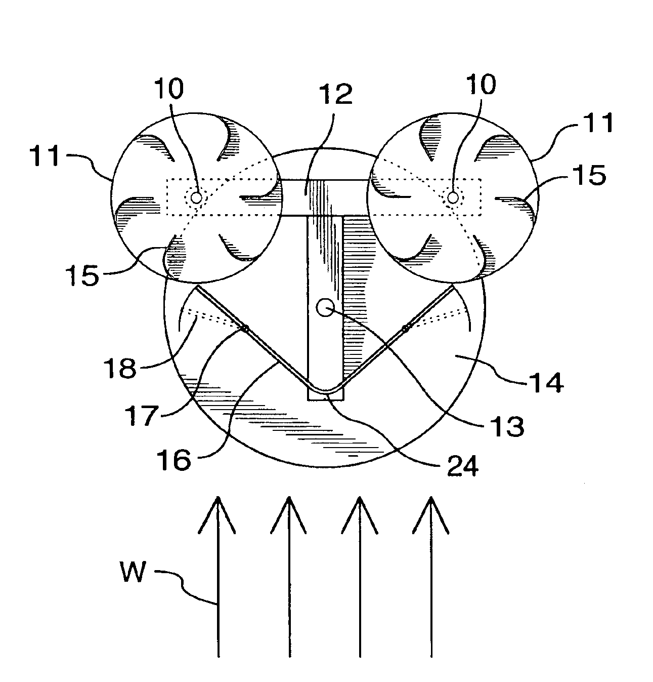
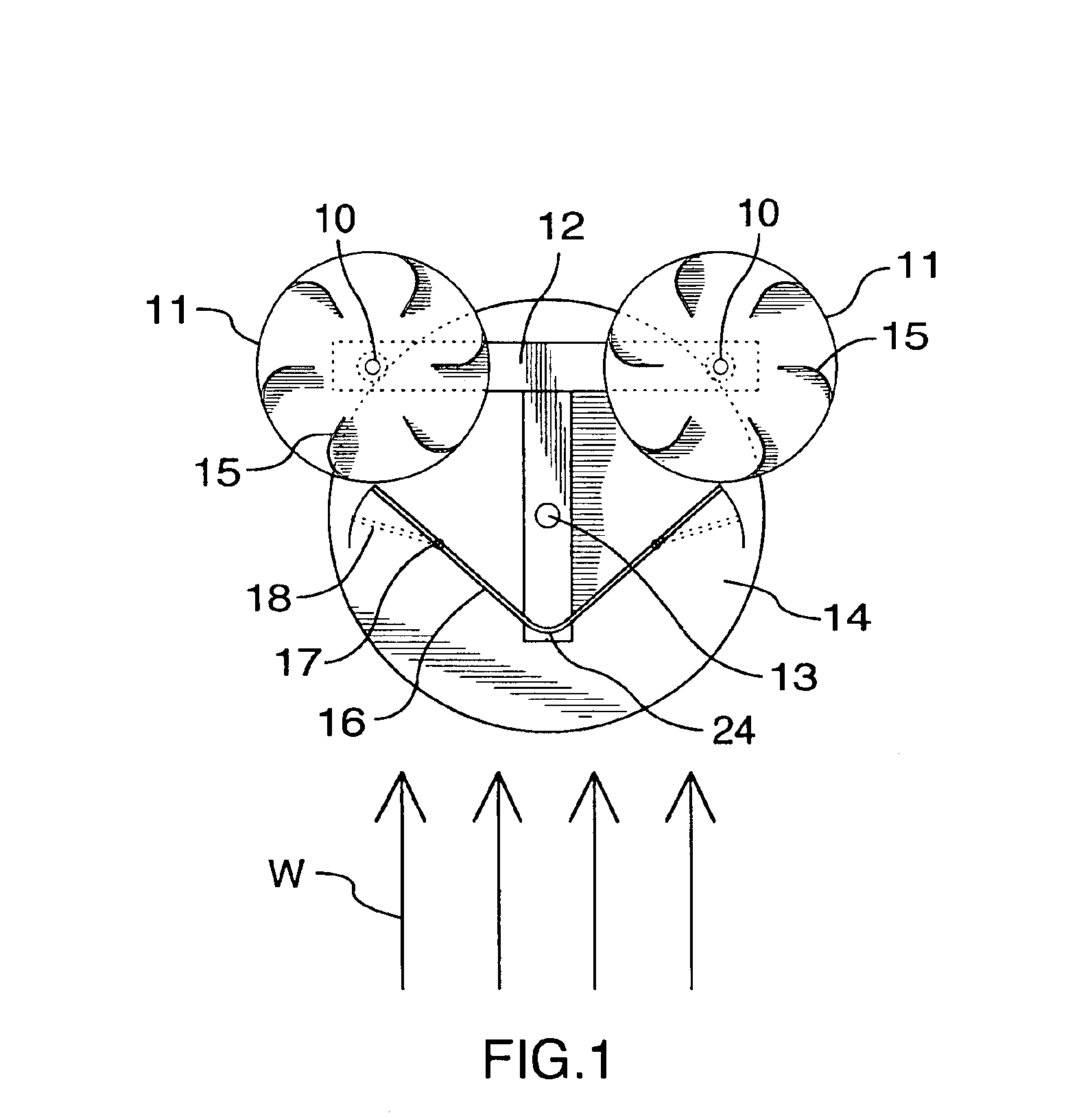
[0031]FIG. 1 is a top view of the vertical axis wind turbine (VAWT), from which the principle of the invention can be readily seen. There are two rotors 11 on a T-shaped support structure 12. Each rotor is mounted on a rotor axis 10. The support structure is rotatable around a center axis 13 on a support platform 14, which in turn will sit on a cylindrical foundation or tower (not shown) of a height determined by topographical parameters. Preferably, the rotors feature six blades 15 each, though that number could vary if desired. One vertical, curved guide vane 16 mounted on the support structure sits centered in front of the two rotors 11. Preferably, two vertical hinges 17 render the two straight ends of the guide vane 16 into deflector flaps 18.

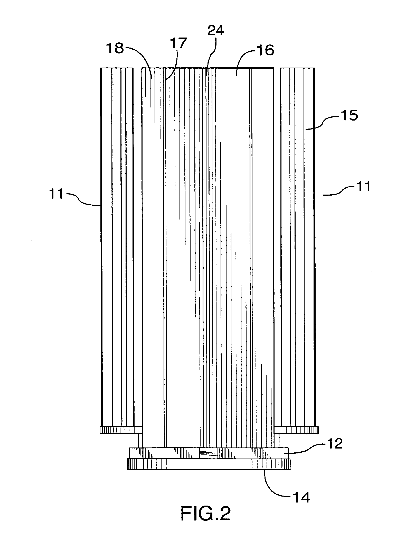
[0032]FIGS. 2-4 are corresponding front, side and perspective views. FIGS. 1-4 are schematic, in that no upper support structure is illustrated, for greater clarity. However, in practice there would be an upper support structure similar to...


PUM


Abstract

The vertical axis wind turbine has two counter-rotating rotors mounted on first and second spaced apart vertical axes. Each rotor has a plurality of rotor blades extending generally inwardly from an outer circumference, the vertical axes being mounted on a support structure which is in turn rotatable on a third vertical axis on a platform. The third axis is spaced from a point midway between the first and second axes in a direction at 90 degrees to and forward from a line between the first and second axes. The vertical axis wind turbine further has a guide vane mounted on the support structure, having a vertex forward of the third vertical axis in the direction at 90 degrees from a line between the first and second axes. The guide vane has left and right symmetrical vane portions extending towards the rotors so as to direct airflow from wind primarily towards portions of the rotors outboard of the first and second axes. The guide vane also tends to keep the vertical axis wind turbine oriented with the guide vane's axis of symmetry pointing forwardly into the wind. Movable deflector flaps pivotally mounted adjacent opposite ends of the vane portions can deflect air at least partially away from the rotors. The structure of the wind turbine can support an unrelated structure such as a restaurant.

Description

REFERENCE TO RELATED APPLICATION[0001]This is a formal application based on and claiming priority from U.S. provisional patent application No. 60 / 430,074, filed Dec. 2, 2002.BACKGROUND OF THE INVENTION[0002]This invention relates to wind turbines, and in particular to wind turbines having a vertical axis.[0003]For eons, wind power has been a source of energy and has been harnessed in various fashions. A profound distinction can be made between horizontal axis wind turbines (HAWTs) and vertical axis wind turbines (VAWTs).[0004]In modern times, the prevalent concept is the HAWT, most frequently with three airfoil blades. While this type of wind turbine claims the highest efficiency, they are burdened with some substantial disadvantages:[0005]a. They are mono-directional, which means they have to be turned into the wind.[0006]b. Their minimum operational wind speed (cut-in speed) is relatively high and the maximum wind speed (cut-out speed) they can endure is relatively low, allowing f...

Claims


Application Information

Patent Timeline
IPC IPC(8): F03D3/04F03D3/02F03D3/00F03D9/00
CPCF03D3/02F03D3/04F03D3/0454F03D9/00F05B2240/40F05B2260/80Y02E10/74F03D3/0445F03D13/20Y02E10/728
Inventor OHLMANN, HANS-ARMIN
Owner OHLMANN HANS ARMIN
Why Eureka
Try Eureka