Magnetic recording medium, production process thereof, and magnetic recording and reproducing apparatus

Inactive Publication Date: 2005-09-13
SHOWA DENKO KK
View PDF2 Cites 25 Cited by
  • Summary
  • Abstract
  • Description
  • Claims
  • Application Information

AI Technical Summary

Benefits of technology

[0023]In view of the foregoing, an object of the present invention is to provide a magnetic recording medium which can attain high

Problems solved by technology

However, when the thickness of the layer is increased, crystal grains of the Al—Ni-based alloy become large.
Therefore, the aforementioned technique encounters difficulty in designing an optimal layer structure for a magnetic recording medium.
However, the Cr alloy crystals arc insufficiently micronized, and a limitation is imposed on reduction of medium noise.
However, when the irregularities are formed on the entire surface of the disk, the

Method used


Image

  • Magnetic recording medium, production process thereof, and magnetic recording and reproducing apparatus
  • Magnetic recording medium, production process thereof, and magnetic recording and reproducing apparatus

Examples


example 1

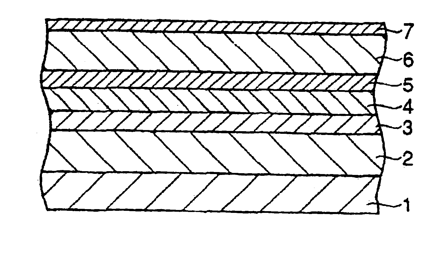
[0101]A glass substrate (outer diameter: 65 mm, inner diameter: 20 mm, thickness: 0.635 mm, surface roughness: 3 Å), serving as a non-magnetic substrate, was placed in a DC magnetron sputtering apparatus (Model: C3010, product of ANELVA, Tokyo, Japan). After the apparatus was evacuated to 2×10⁻⁷ Torr (2.7×10⁻⁵ Pa), a first non-magnetic undercoat layer (layer A) (thickness: 200 Å) was formed at ambient temperature by use of a target containing a Cr—Ta-based alloy (Cr: 65 at %, Ta: 35 at %). Subsequently, a second non-magnetic undercoat layer (layer B) (thickness: 200 Å) was formed at ambient temperature by use of a target containing a Co—W—B-based alloy (Co: 57 at %, W: 40 at %, B: 3 at %).

[0102]Thereafter, the substrate was heated to 250° C., and then exposed to oxygen at 0.05 Pa for five seconds. Subscqucntly, a third non-magnetic undercoat layer (layer C) (thickness: 60 Å) was formed by use of a target containing a Cr—Ti alloy (Cr: 80 at %, Ti: 20 at %), A non-magnetic intermediat...

example 2

[0105]The procedure of Example 1 was repeated, except that a first non-magnetic undercoat layer (thickness: 200 Å) was formed by use of a target containing a Cr—Nb-based alloy (Cr: 65 at %, Nb: 35 at %) instead of the Cr—Ta-based alloy (Cr: 65 at %, Ta: 35 at %).

example 3

[0106]The procedure of Example 1 was repeated, except that a first non-magnetic undercoat layer (thickness: 200 Å) was formed by use of a target containing a Cr—Ti-based alloy (Cr: 65 at %, Ti: 35 at %) instead of the Cr—Ta-based alloy (Cr: 65 at %, Ta: 35 at %).


PUM


Abstract

A magnetic recording medium comprises a non-magnetic substrate, a non-magnetic undercoat layer, a magnetic layer, and a protective film, the layers and film being successively formed on the substrate. The non-magnetic undercoat layer has a multi-layer structure formed of at least two layers and contains a layer A formed of a material selected from a Cr—Ta based alloy, a Cr—Nb-based alloy, a Cr—Ti based alloy, a Cr—Zr-based alloy, and a Cr—Hf-based alloy, and a layer B formed of a material selected from a Co—W based alloy, a Co—W—B-based alloy, a Co—Mo based alloy, a Co—Mo—B based alloy, a Co—W—Mo based alloy, and a Co—W—Mo—B based alloy. The layers A and B are provided in this order from the non-magnetic substrate. A process for producing the medium comprises exposing the surface of the layer B to an oxygen atmosphere.

Description

CROSS-REFERENCE TO RELATED APPLICATIONS[0001]This application claims benefit of Provisional Application 60 / 394,931 filed Jul. 11, 2002, incorporated herein by reference, under 35 U.S.C. § 111(b) pursuant to 35 U.S.C. § 119(e) (1).BACKGROUND OF THE INVENTION[0002]1. Field of the Invention[0003]The present invention relates to a magnetic recording medium which is employed in, for example, hard disk devices, to a process for producing the magnetic recording medium, and to a magnetic recording and reproducing apparatus.[0004]2. Background Art[0005]The recording density of a hard disk device (HDD), which is a magnetic recording and reproducing apparatus, has increased at a rate of 60% per year, and this tendency is expected to continue. Therefore, magnetic recording heads and magnetic recording, media which are suitable for attaining high recording density are now under development.[0006]Magnetic recording media employed in hard disk devices are required to have high recording density, a...

Claims


Application Information

Patent Timeline
IPC IPC(8): G11B5/73G11B5/84G11B5/62
CPCG11B5/7325G11B5/8404G11B5/7369G11B5/73911G11B5/73921
Inventor OSAWA, HIROSHI
Owner SHOWA DENKO KK
Why Eureka
Try Eureka