Apparatus for and method of measuring power consumption

a technology of power consumption and apparatus, applied in the field of apparatus for measuring power, can solve the problems of not considering the actual power consumption of the product, and consumers have not had a way to know the actual power consumption of the current produ

Inactive Publication Date: 2005-09-13
SAMSUNG ELECTRONICS CO LTD
View PDF4 Cites 15 Cited by
  • Summary
  • Abstract
  • Description
  • Claims
  • Application Information

AI Technical Summary

Benefits of technology

[0017]According to an aspect of the present invention, where the voltage regulating unit regulates the voltage at the primary coil of the transforming unit to calculate the turn-on time of the switching unit, the voltage regulating unit may comprise a voltage decreasing section which decreases the voltage at the primary coil of the transforming unit below a certain level, a first clamp which clamps the decreased voltage at a first constant voltage level, a transformer which transforms the first clamped voltage, and a second clamp which clamps the transformed voltage at a second constant voltage level.
[0018]According to an aspect of the present invention where the voltage regulating unit regulates the voltage at the secondary coil of the transforming unit to calculate the turn-on time of the switching unit, the voltage regulating unit may comprise a voltage decreasing section which decreases the voltage at the secondary coil of the transforming unit below a certain level, and a clamp which clamps the output of the voltage decreasing section at a constant voltage level.

Problems solved by technology

Displaying the actual power consumption has not been considered due to the complexity of a circuit needed to implement such a function and cost.
Further, consumers have not had a way to know the actual power consumption of a currently used product other than the maximum power consumption stated in the product manual or on a label attached to the product.

Method used


Image

  • Apparatus for and method of measuring power consumption
  • Apparatus for and method of measuring power consumption
  • Apparatus for and method of measuring power consumption

Examples


first embodiment

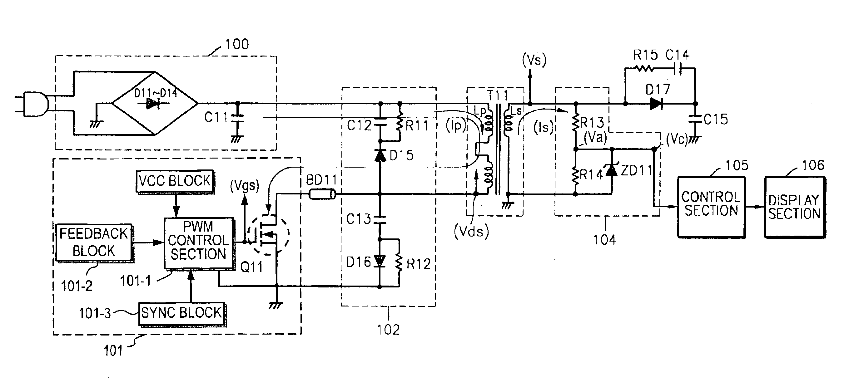
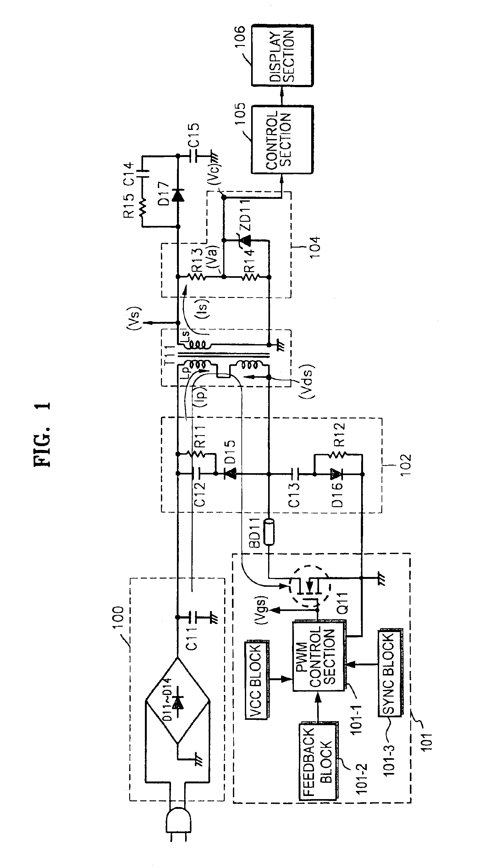
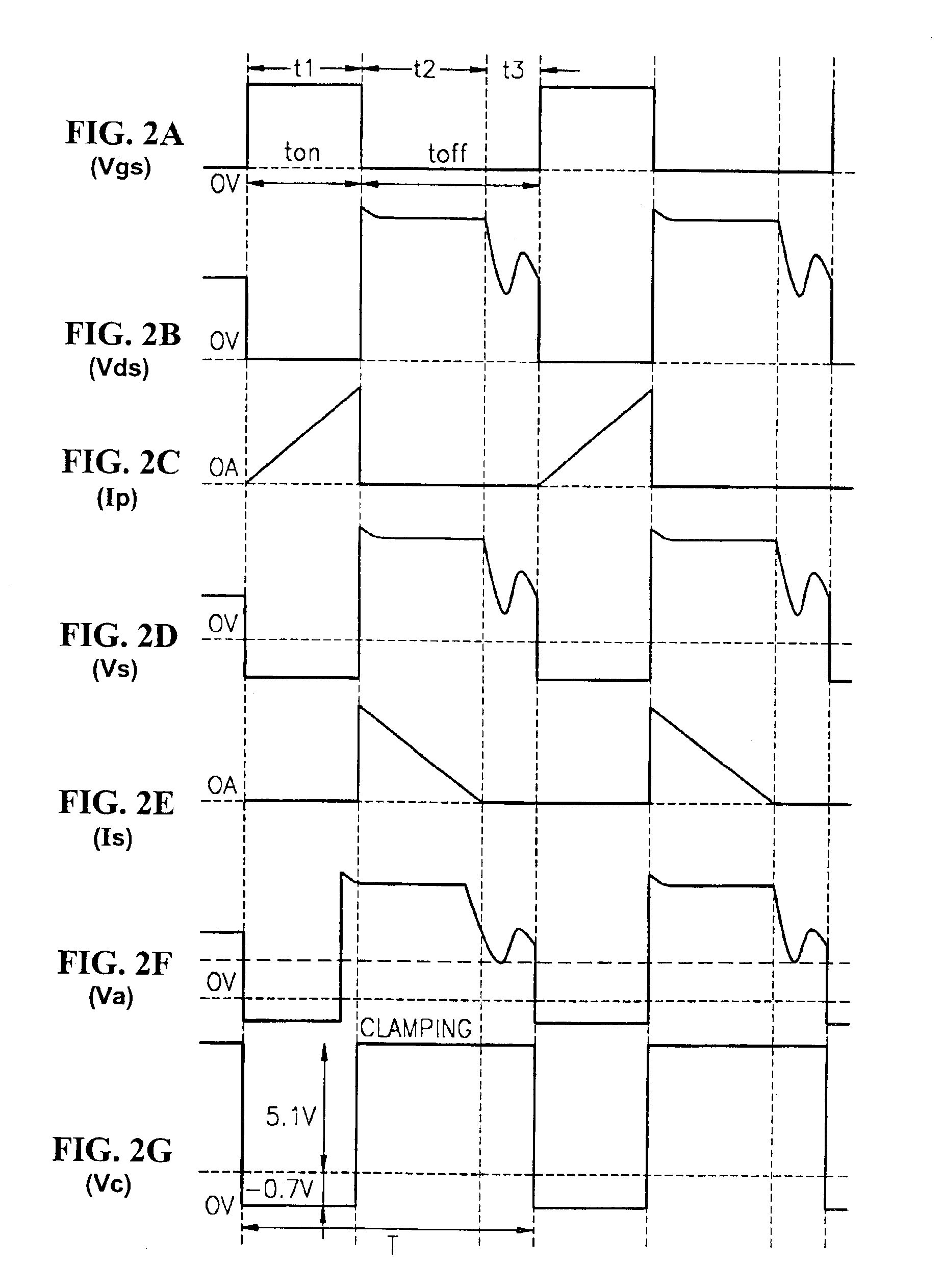
[0025]With reference to FIGS. 1 and 2A-2G, a method of measuring power consumption using the voltage Vs at the secondary coil of the transformer T11 will be described below. FIG. 1 is a circuit diagram of an apparatus for measuring power consumption according to the present invention. The apparatus shown in FIG. 1 comprises a rectifying section 100, a switching section 101, a snubber circuit 102, a transformer T11, a voltage regulating section 104, a control section 105, and a display section 106.

[0026]The rectifying section 100 rectifies and smoothes input AC current power to produce a DC voltage. The smoothed DC voltage is applied to a first end of a primary coil of the transformer T11. The switching section 101 switches on or off the voltage output at a second end of the primary coil of the transformer T11 with pulse-width modulation (PWM) control signals. The switching section 101 comprises a PWM control section 101-1 which generates PWM signals based on feedback voltages from a...

second embodiment

[0037]With reference to FIGS. 3 and 4A through 4I, a method of measuring power consumption using a voltage Vds at a primary coil of a transformer 303 will be described below. FIG. 3 is a circuit diagram of an apparatus for measuring power consumption according to the present invention. The apparatus shown in FIG. 3 comprises, a rectifying section 300, a switching section 301, a snubber circuit 302, the transformer T31, a voltage regulating section 304, a control section 305, and a display section 306.

[0038]The rectifying section 300 rectifies and smoothes input AC current power to produce a DC voltage. The smoothed DC voltage is applied to a first end of a primary coil Lp of the transformer T31. The switching section 301 switches on or off the voltage output at a second end of the primary coil of the transformer T31 with PWM control signals. The switching section 301 comprises a PWM control section 301-1 which generates PWM signals based on feedback voltages from a feedback block 30...


PUM


Abstract

An apparatus for and a method of measuring, in real-time, and indicating power consumption of a product powered by a switching mode power supply (SMPS). Power is supplied to the product through a transformer having a predetermined primary coil inductance, wherein a current of a primary coil of the transformer is turned ON and OFF by pulse-width modulation to supply the power to the electronic device. A drive voltage across the primary coil is monitored and a pulse waveform having a first level corresponding to an ON time of the current in the primary coil and a second level corresponding to an OFF time of the current in the primary coil is developed. Power consumption is calculated based on the drive voltage, the ON time of the current in the primary coil, the predetermined primary coil inductance, and a switching frequency of a pulse width modulator of the SMPS.

Description

BACKGROUND OF THE INVENTION[0001]This application claims the priority of Korean Patent Application No. 2002-52825, filed Sep. 6, 2002, in the Korean Intellectual Property Office, the disclosure of which is incorporated herein by reference.[0002]1. Field of the Invention[0003]The present invention relates to an apparatus for measuring power and, more particularly, to an apparatus for measuring, in real-time, and indicating power consumption of a product using a switching mode power supply (SMPS).[0004]2. Description of the Related Art[0005]Power consumption is a quantitative indication of the ratio of how much energy is consumed or how much work is done per unit of time, and indicates the amount of energy supplied or consumed in a unit second. An energy consumption efficiency grade of a product varies in accordance with the consumption power, and a low-grade product wastes energy during the entire life of the product. Therefore, it is desirable to confirm the energy consumption effic...

Claims


Application Information

Patent Timeline
Patent Type & Authority Patents(United States)
IPC IPC(8): G01R21/00G01R21/127H04N5/63G01R21/06H02M3/28
CPCG01R21/127H04N5/63
Inventor CHOI, YOUNG-HUN
Owner SAMSUNG ELECTRONICS CO LTD
Why Eureka
Try Eureka