Bulk acoustic wave filter with a roughened substrate bottom surface and method of fabricating same

a filter and substrate technology, applied in the direction of piezoelectric/electrostrictive transducers, generators/motors, transducers, etc., can solve the problems of deteriorating performance, leaking acoustic energy into the substrate, and incomplete acoustic isolation of the resonator by the acoustic mirror, so as to reduce the effect of acoustic energy reflection in the substra

Inactive Publication Date: 2005-09-13
NOKIA CORP +1
View PDF13 Cites 44 Cited by
  • Summary
  • Abstract
  • Description
  • Claims
  • Application Information

AI Technical Summary

Benefits of technology

[0017]Accordingly, there is a demand for acoustic filter devices in which the deteriorating effects caused by reflection of acoustic energy in the substrate is reduced.
[0018]Especially, there is a demand for a cost-effective solution which can be easily integrated into standard CMOS production processes.
[0024]c) roughening the bottom surface of the substrate such that the reflection of an acoustic wave back to the Bulk Acoustic Wave filter is reduced.
[0028]The effect achieved by the roughening of the bottom surface of the substrate is that an acoustic wave which is generated by the acoustic wave filter and reaches the bottom surface of the substrate, is basically scattered at the roughened bottom surface. Accordingly the portion of the acoustic wave that is actually reflected back to the acoustic wave device is reduced which, in turn, improves the performance characteristics of the acoustic wave filter. In that manner, the acoustic wave filter may reach performance levels similar to those of a bridge-type filter but avoids the disadvantages of bridge-type filters with regard to the production complexity.
[0033]The filter devices according to the present invention allow a significant reduction of the number of mirror layers necessary to acoustically isolate the substrate from the acoustic wave filter. It may even be possible to omit the acoustic mirror completely. The reduction of the number of mirror layers used reduces the cost of the filter device and furthermore makes it possible that the acoustic mirror is optimized regarding other parameters than reduction of reflection within the substrate, such as, for instance, temperature behavior.
[0034]In a further aspect of the present invention a method for fabricating a filter device is provided, comprising the steps of a) providing a substrate having a top surface and a bottom surface, b) forming at least one acoustic wave filter device on the top surface of the substrate, and c) roughening the bottom surface of the substrate such that the reflection of an acoustic wave back to the acoustic wave filter is reduced.

Problems solved by technology

A problem encountered with solidly mounted Bulk-Acoustic-Devices is that the acoustic isolation of the resonator by the acoustic mirror is not complete and that therefore a part of the acoustic energy leaks into the substrate and is reflected from the bottom surface of the substrate back up to the resonator.
This phenomena causes ripples in the filter's passband, deteriorating it's performance.
For some frequencies, depending on the thickness of the substrate, the substrate may even form an acoustic cavity, which increases the negative effects on the resonators.
The problem with this solution is that glass substrates are not compatible with standard CMOS production processes.
Unfortunately, both these solutions cause considerable additional costs in the production of such devices.
However, the costs for fabricating such bridge-type BAW resonators is much higher than for those using acoustic mirrors.
Furthermore, the use of bridge-type resonators puts further constraints regarding suitable packaging of such filter devices.

Method used


Image

  • Bulk acoustic wave filter with a roughened substrate bottom surface and method of fabricating same
  • Bulk acoustic wave filter with a roughened substrate bottom surface and method of fabricating same
  • Bulk acoustic wave filter with a roughened substrate bottom surface and method of fabricating same

Examples


Embodiment Construction

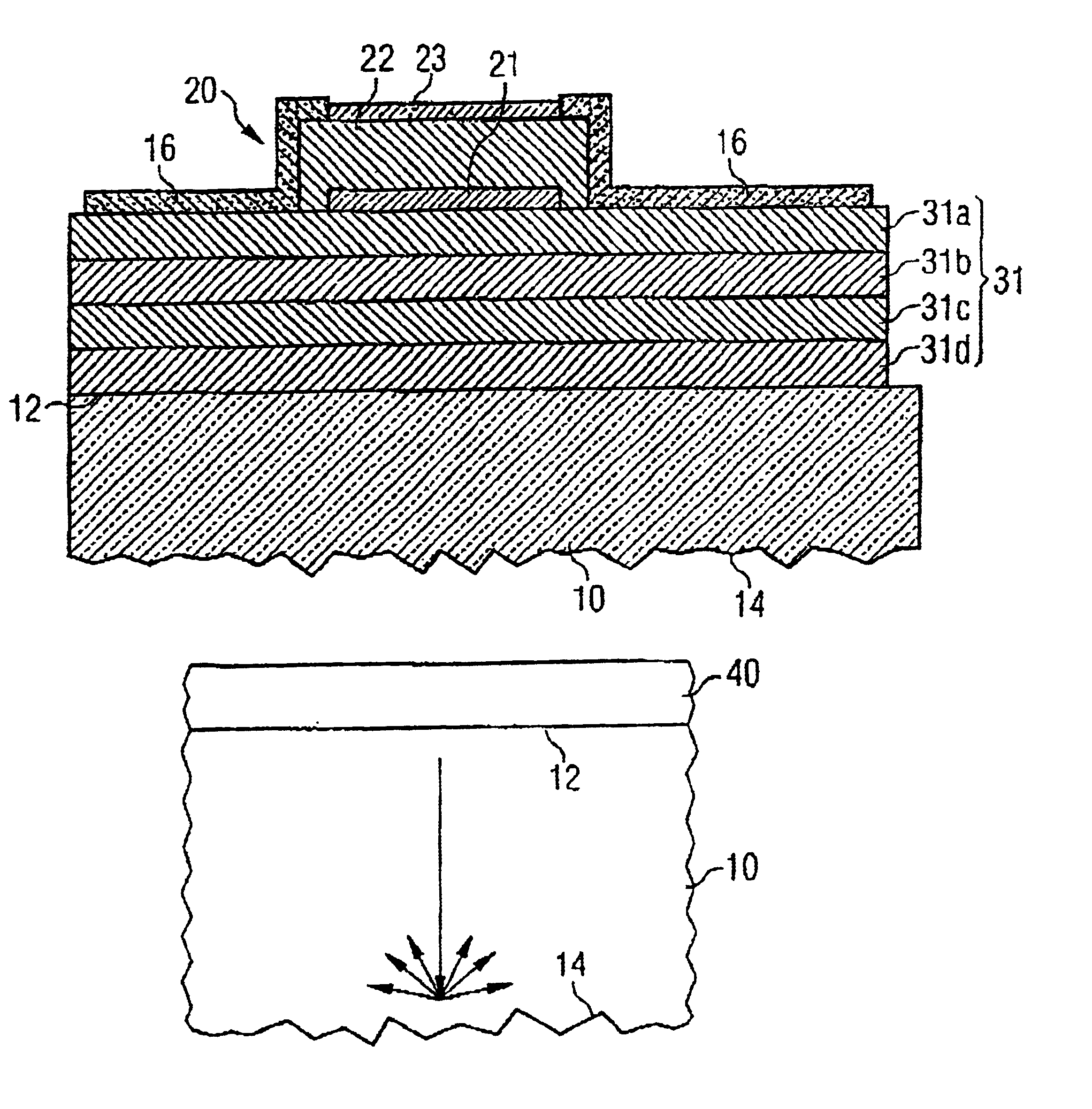
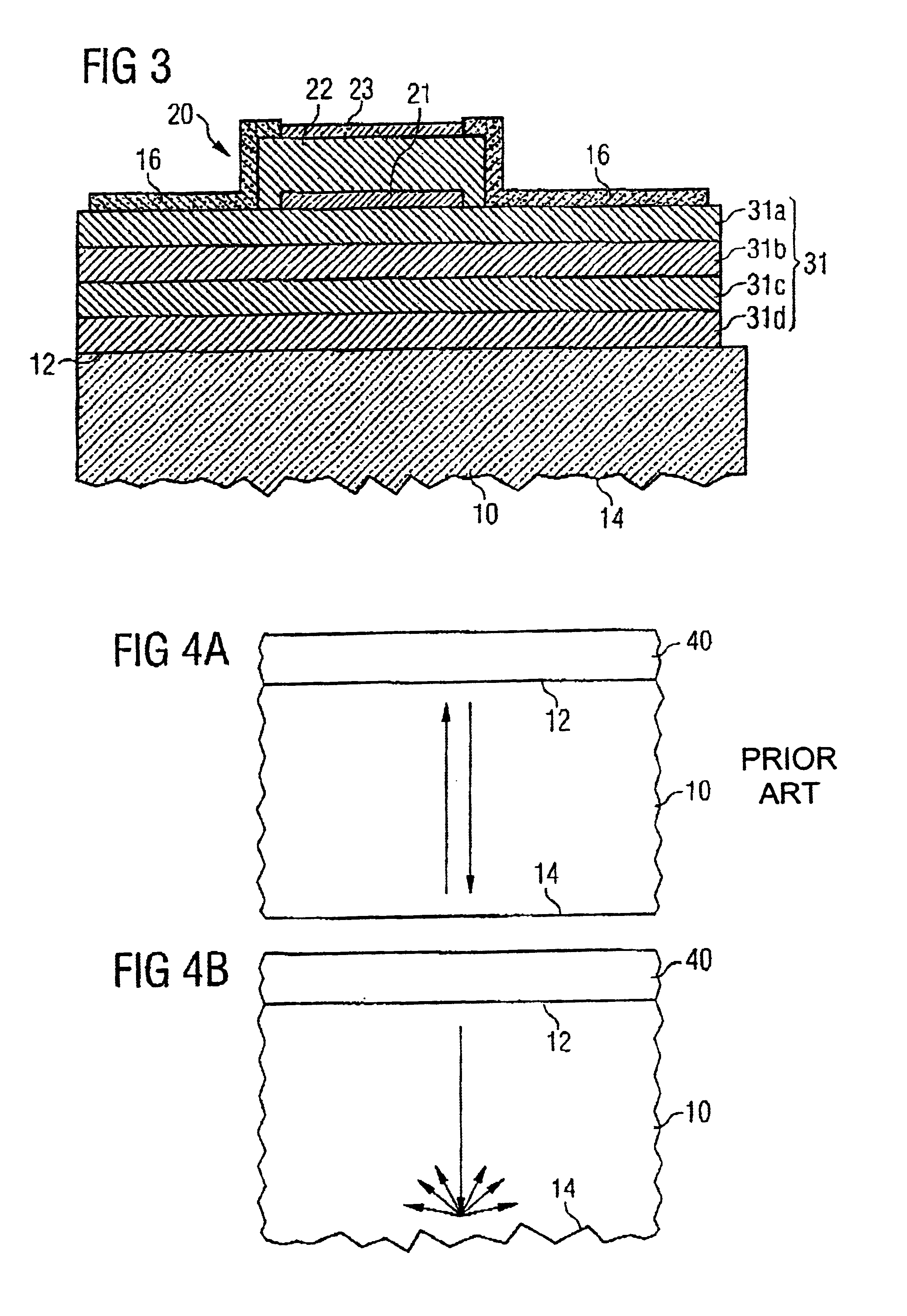
[0052]FIG. 3 shows a resonator comprised in an acoustic wave filter used in a filter device according to a first embodiment of the present invention.

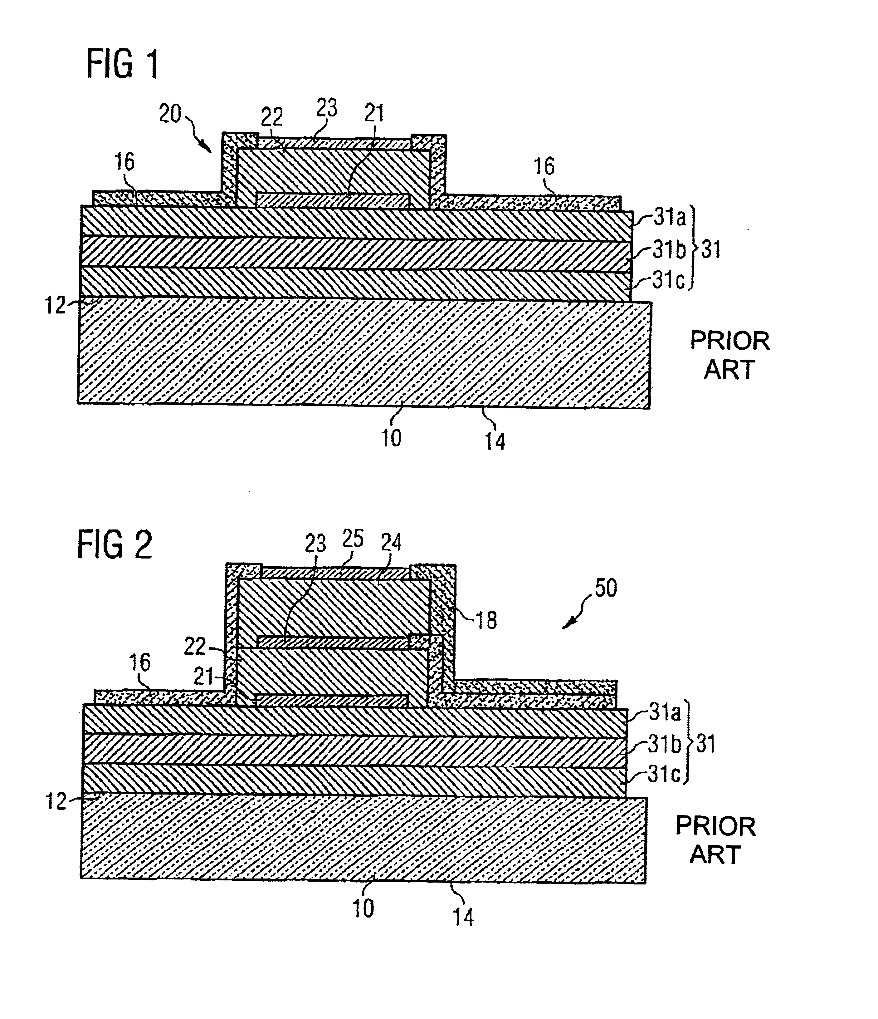
[0053]The resonator shown in FIG. 3 is a bulk acoustic wave resonator and essentially corresponds to the one described with respect to FIG. 1 of this application. Corresponding reference numerals in FIG. 3 denote parts corresponding to those of FIG. 1.

[0054]Contrary to the bulk acoustic resonator disclosed in FIG. 1 the resonator according to FIG. 3 comprises a substrate (10) in which the bottom surface of the substrate (14) has been roughened such that the reflection of an acoustic wave back to the acoustic wave filter is reduced. Thereby, the average height difference between the peaks and the valleys on the roughened bottom surface of the substrate is larger than 0.2λ, preferably larger than 0.5λ. In typical applications the average height difference between the peaks and the valleys is larger than 2 μm, preferably larger than 3 μm a...


PUM

PropertyMeasurementUnit
resonance frequencyaaaaaaaaaa
heightaaaaaaaaaa
heightaaaaaaaaaa

Abstract

A filter device comprises a substrate having a top surface and a bottom surface, and at least one acoustic wave situated on the top surface of the substrate, wherein the bottom surface of the substrate is roughened to reduce the reflection of an acoustic wave back to the acoustic wave filter. The effect achieved by the roughening of the bottom surface of the substrate that an acoustic wave which is generated by the acoustic wave filter and reaches the bottom surface of the substrate, is basically scattered so the acoustic wave that is actually reflected back to the acoustic wave device is reduced which, in turn, improves the performance characteristics of the acoustic wave filter.

Description

CROSS REFERENCE TO RELATED APPLICATION[0001]This application is a continuation of copending International Application No. PCT / EP01 / 12826 filed Nov. 6, 2001 which designates the United States.TECHNICAL FIELD OF THE INVENTION[0002]The present invention generally relates to filter devices. The present invention especially relates to acoustic wave filter devices, e. g. Surface Acoustic Wave (SAW) filter devices, and / or Bulk Acoustic Wave (BAW) filter devices.DESCRIPTION OF RELATED ART AND BACKGROUND OF THE INVENTION[0003]The need for using miniature and high performance filters in wireless communication devices has led to the widespread usage of Surface Acoustic Wave (SAW) filters. In addition to Surface Acoustic Wave (SAW) filters Bulk Acoustic Wave (BAW) filters can also be used. Bulk Acoustic Wave (BAW) filters typically include several Bulk Acoustic Wave(BAW) resonators. In a Bulk Acoustic Wave (BAW) filter, acoustic waves propagate in a direction that is perpendicular to the filter...

Claims


Application Information

Patent Timeline
Patent Type & Authority Patents(United States)
IPC IPC(8): H03H3/02H03H9/00H03H9/17H03H3/00H03H9/02H03H9/58
CPCH03H3/02H03H9/02055H03H9/0211H03H9/585H03H9/589H03H9/175Y10T29/42
Inventor AIGNER, ROBERTTIKKA, PASIELLA, JUHA SAKARI
Owner NOKIA CORP
Why Eureka
Try Eureka