Synchronizing clocks across a communication link

a technology of communication link and synchronization clock, which is applied in the direction of network traffic/resource management, wireless commuication services, and assessing restrictions, etc., can solve the problem of not having direct access to the side of the link, and achieve the effect of more accurate and/or faster data transfer

Inactive Publication Date: 2005-09-13
WI LAN INC
View PDF29 Cites 83 Cited by
  • Summary
  • Abstract
  • Description
  • Claims
  • Application Information

AI Technical Summary

Benefits of technology

[0013]Particular embodiments of the present invention include a millimeter wave wireless RF channel communications system which connects single base stations each to a plurality of relatively proximate Customer Premise Equipment (CPE) stations. A network of such base stations with their surrounding CPEs can provide all communications services over a large ...

Problems solved by technology

However, the network clock on one side of the link does not have direct access to the network clock on the other side of the l...

Method used


Image

  • Synchronizing clocks across a communication link
  • Synchronizing clocks across a communication link
  • Synchronizing clocks across a communication link

Examples


Embodiment Construction

1. Data Links and Network Clocks

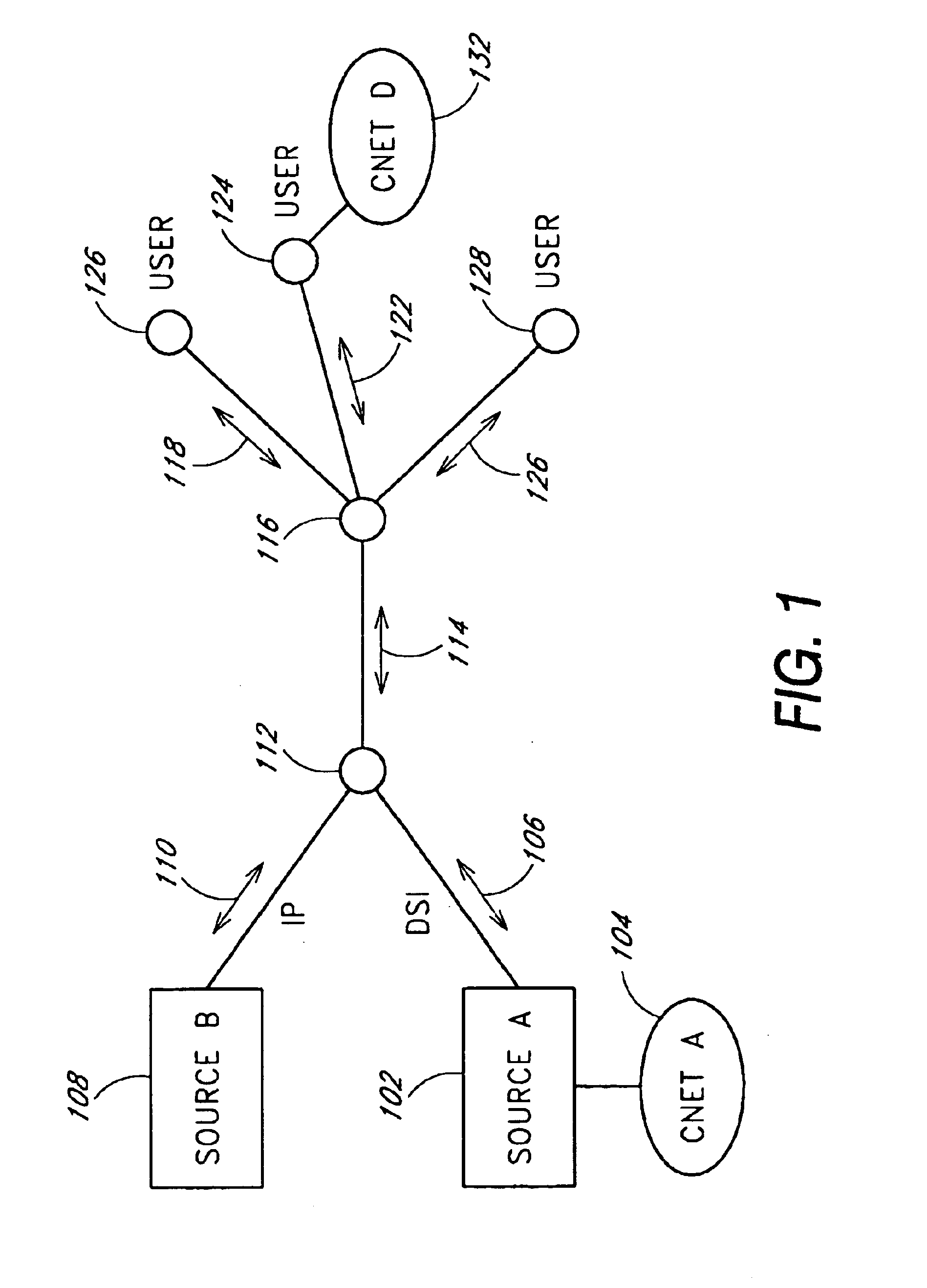
[0032]Data typically travels through a network in packets, from node to node across links. A data source can be identified, though not necessarily the original source, which determines the rate at which the data is received. Referring to FIG. 1, a SourceA 102 provides data 106 to the network 130. Data 106 includes some fixed-rate data streams, such as a DS1 (also called T1) telephony connection. A network clock 104, CNetA which is local to SourceA, determines the precise rate at which such data is provided into the network 130. A SourceB 108 represents a source of data 110 which is not necessarily supplied at a fixed rate, and may include for example Internet Protocol (IP) packets. The data from these sources is merged at node 112. Node 112 may be a switch which reformats the incoming data into a format such as ATM cells. In any event, the combined data 114 is then transferred to another node 116, from whence the data is distributed appropriately to u...


PUM


Abstract

Apparatus, system and method for synchronizing one or more clocks across a communication link. A slave clock may be synchronized to a master clock by means of a synchronization signal sent from the master to the slave clock side of the link. The synchronization signal may be an expected signal pattern sent at intervals expected by the slave side. The slave clock may correlate received signals with a representation of the expected synchronization signal to produce a correlation sample sequence at a first sample rate which is related as n times the slave clock rate. The synchronization signal receipt time indicated by the correlation sample sequence may be refined by interpolating the correlation sample sequence around a best correlation sample to locate a best interpolation at an interpolation resolution smaller than the sample resolution. The best interpolation may in turn be further refined by estimating between interpolator outputs adjacent to the best interpolation output. The synchronization signal receipt time thus determined is compared to the expected time based upon the slave clock, which is adjusted until the times match. After initialization, all slave clock errors are preferably accumulated to prevent long-term slip between the slave and master clocks. Formerly independent master and slave clocks synchronized across the communication link constitute a noncommon clock which may be compared on each side of the link to secondary independent clocks, and the secondary independent clocks may then be separately synchronized by adjusting one to have the same difference from its local noncommon clock as the secondary clock on the other side of the link has from its local noncommon clock.

Description

CROSS REFERENCE TO RELATED APPLICATIONS[0001]This invention is related to commonly assigned co-pending U.S. patent application Ser. No. 09 / 316,518, filed May 21, 1999, entitled “Method and Apparatus for Allocating Bandwidth in a Wireless Communication System,” which is hereby incorporated in its entirety by reference.FIELD OF THE INVENTION[0002]This invention relates to data communication systems, and to synchronizing independent clocks between nodes of such systems.BACKGROUND[0003]Data communication systems typically transfer data from a source to an end user by routing the data in packets through a series of nodes connected by links. It is generally faster to transfer data synchronously, when circumstances permit, and yet in many instances communication system links do not share an explicit clock. In the typical circumstance that the clocks at different node are independent, and yet synchronous data transfer timing is desired. Moreover, demodulating a modulated data signal can be ...

Claims


Application Information

Patent Timeline
IPC IPC(8): H04J3/06H04L12/56H04L7/04H04L7/08
CPCH04J3/0658H04L7/042H04L7/08H04W28/04H04W48/08H04W56/00H04W84/20
Inventor SINHA, PRANESHAKLER, SHARONBOURLAS, YAIRGALLAGHER, TIMOTHY LEOGILBERT, SHELDON L.POLLMANN, STEPHEN C.PRICE, FREDERICK W.READLER, BLAINE C.WISS, JOHNARVIV, ELL
Owner WI LAN INC
Why Eureka
Try Eureka