Stylet feature for resisting perforation of an implantable lead

a technology of perforation and stylet, which is applied in the direction of catheters, guide wires, therapy, etc., can solve the problems of increased force, increased risk, and increased risk inherent in the procedure, and achieves the effect of reducing the risk of perforation

Inactive Publication Date: 2005-09-13
PACESETTER INC
View PDF17 Cites 23 Cited by
  • Summary
  • Abstract
  • Description
  • Claims
  • Application Information

AI Technical Summary

Benefits of technology

[0011]According to the invention, an enlarged, elongated feature is incorporated at the distal end of the stylet. This feature is designed in such a manner that the force exerted by the surgeon is distributed over a larger surface area at the tip of the stylet. This reduces the pressure at any given point at the distal tip of the stylet and therefore reduces the risk of the stylet perforating the lead. The tapering of the stylet wire at the distal end further enhances this feature. The taper softens the resistance of the stylet to follow the bends in the venous system.
[0012]This combination of a larger surface area at the distal tip and tapering the wire to soften the bending resistance will lead to a greater reduction of stylet perforation through the lead. Furthermore, the larger surface area will more easily cross the gaps in the coil windings and resist piercing through them. The larger surface area will also resist distorting the PTFE tubing as the stylet passes through the tubing and will therefore resist piercing through it.
[0015]Yet another feature of the present invention is the provision of such a unique stylet which offers a surgeon, while in the midst of the surgical procedure, with the ability to choose whether to proceed with the use of a stylet in one instance or with the use of a guidewire in another instance.

Problems solved by technology

The problem is that, previously, it was necessary for the surgeon to choose which method to use prior to surgery.
However, there are risks that are inherent to the procedure just mentioned.
These bends can create a strain on the lead and require a greater force to drive the lead.
The stylet then has the risk of passing in between the coil windings of the lead or piercing the PTFE and perforating the lead.
This perforation is dangerous to the patient.

Method used


Image

  • Stylet feature for resisting perforation of an implantable lead
  • Stylet feature for resisting perforation of an implantable lead
  • Stylet feature for resisting perforation of an implantable lead

Examples


Embodiment Construction

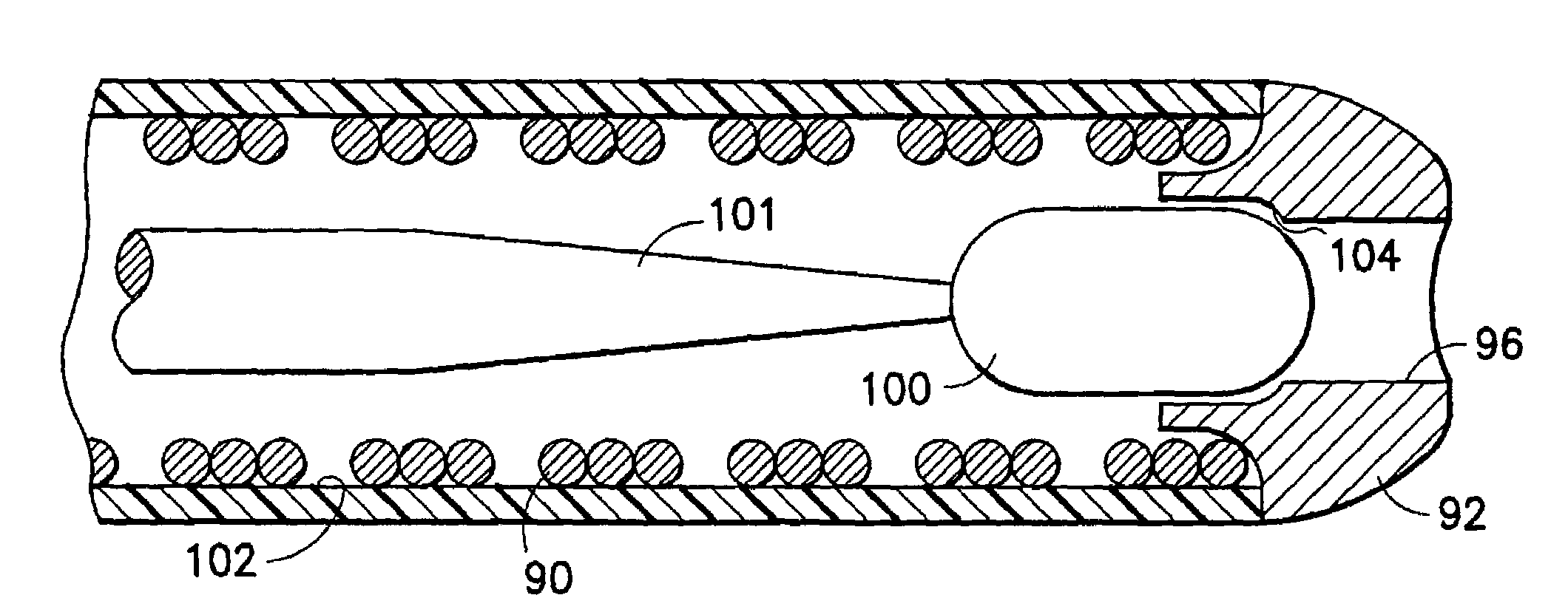
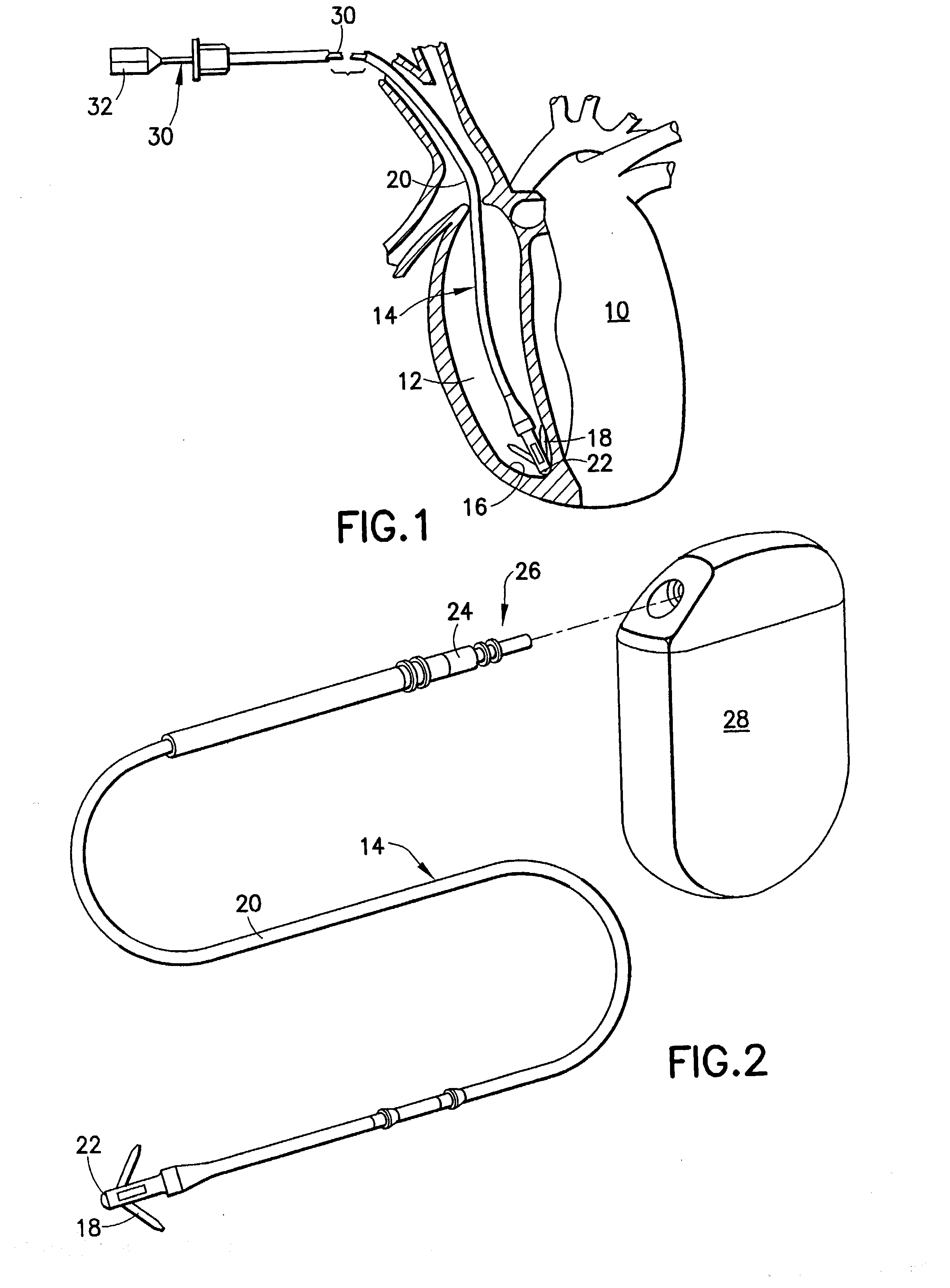
[0031]Referring to FIG. 1, there is shown a diagrammatic elevation view partially cut away and shown in section of a heart 10 into the right ventricle 12 of which is inserted a body implantable lead system 14 of the endocardial type incorporating features of the present invention. Although the present invention will be described with reference to the embodiments shown in the drawings, it should be understood that the present invention may be embodied in many alternate forms or embodiments. For example, while the illustrated lead system is of the passive fixation variety, it is within the scope of this invention that it be of the active fixation variety. In addition, any suitable size, shape or type of elements or materials consistent with the invention could be used. In this instance, the lead system 14 is attached to an interior wall 16 of the heart 10 by means of fixing tines 18 which engage the tissue or trabeculae of the heart.

[0032]As further illustrated, the lead system 14 als...


PUM


Abstract

A stylet unit for implanting a removable lead system for a cardiac stimulation device includes an elongated main body having an enlarged feature at the distal end of the main body with a rounded blunt tip end, a width greater than the width of the distal end of the main body, and a length greater than the width. A finger grip is provided at a proximal extremity of the elongated main body for manipulating the stylet unit. Lead system includes an elongated tubular lead body containing an elongated coil conductor with a plurality of coil windings defining a passageway extending the length of the coil conductor and having inner surfaces facing toward the passageway. The enlarged feature of the stylet is sufficiently long to assure that it advances along the passageway in slidable engagement with the inner surfaces of the coil conductor but without thrusting between adjoining coils.

Description

FIELD OF THE INVENTION[0001]The present invention relates to implantable leads for use with a cardiac stimulation device and, more particularly, to stylets which are used to facilitate the implantation of the lead into the body.BACKGROUND OF THE INVENTION[0002]Surgeons have implanted leads into the coronary sinus of the heart of a patient by using one of two methods to drive and position the lead. One method is to utilize a stylet to push the lead tip through the venous system when the stylet is fully inserted into the lead. The other method is to slide the lead over a guidewire. The lead has openings at each end through which the guidewire passes. The guidewire is positioned into the coronary sinus and the lead is then moved into position by sliding over the guidewire. Each method has its benefits. The problem is that, previously, it was necessary for the surgeon to choose which method to use prior to surgery.[0003]Also, cardiac pacing and / or defibrillation leads are constructed ge...

Claims


Application Information

Patent Timeline
Patent Type & Authority Patents(United States)
IPC IPC(8): A61N1/05
CPCA61N1/05A61M2025/09175A61N1/056
Inventor MORGAN, KEVIN L.FLORIO, JOSEPH J.
Owner PACESETTER INC
Why Eureka
Try Eureka