Wireless communication system for vehicle

a communication system and vehicle technology, applied in the field of vehicle wireless communication system, can solve the problems of inconvenience of devices, spoiled timeliness, and difficulty in setting the predetermined time to enable the power window function, so as to improve convenience, improve convenience, and be convenient to us

Inactive Publication Date: 2005-09-13
CALSONIC KANSEI CORP
View PDF12 Cites 34 Cited by
  • Summary
  • Abstract
  • Description
  • Claims
  • Application Information

AI Technical Summary

Benefits of technology

[0017]When the sub-controller further includes an operation input section for controlling the vehicle mounted electronic device, and an operable time of the operation input section is extended by a predetermined time while the sub-controller continuously receives the instruction from the main controller, convenience can be improved.
[0018]When the actuator is set as a motor for driving a power window and the operation input section is set as a power window switch, the power window can be easily used at any time even in the case where a driver has done some work after turning off the ignition switch or has done some work in the vicinity of the door left open. Accordingly, convenience can be improved.

Problems solved by technology

The device, however, has given a sense of inconvenience because the portable key 1 is provided with the operating switches 1a and 1b so that either of the operating keys 1a and 1b must be externally operated with a finger tip or the like to be turned on.
How to set the predetermined time to enable the power window function, however, becomes a problem in this case.
The check, however, involves a certain amount of time so that timeliness is spoiled due to occurrence of a time loss before the power window is actuated.
This may make the driver impatient and result in problems such as damage to salability.

Method used


Image

  • Wireless communication system for vehicle
  • Wireless communication system for vehicle
  • Wireless communication system for vehicle

Examples


Embodiment Construction

[0026]Referring now to the accompanying drawings, a description will be given in detail of a preferred embodiment of the invention.

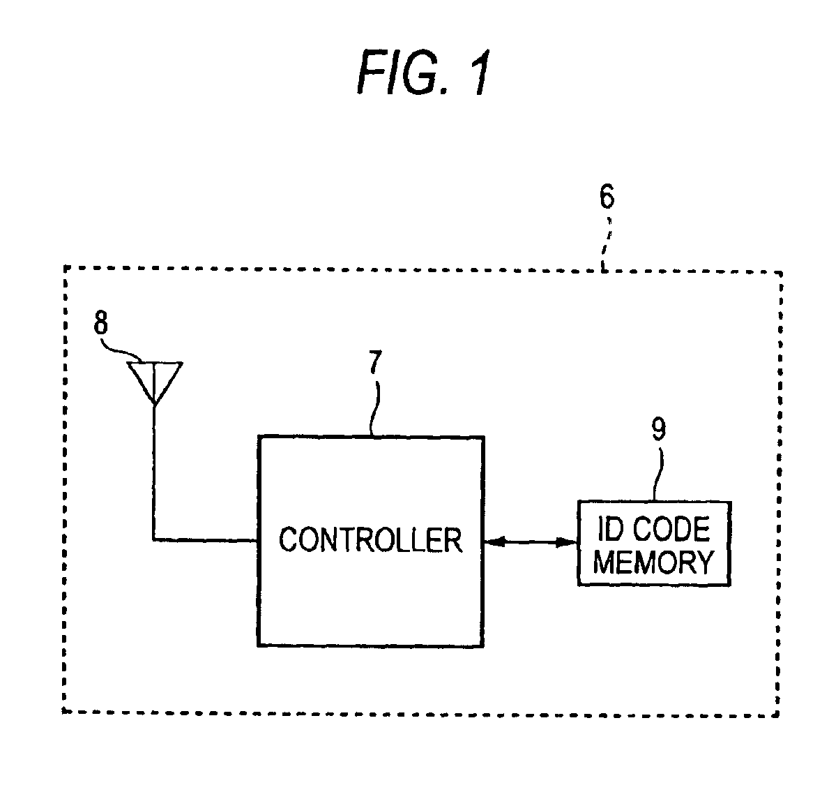
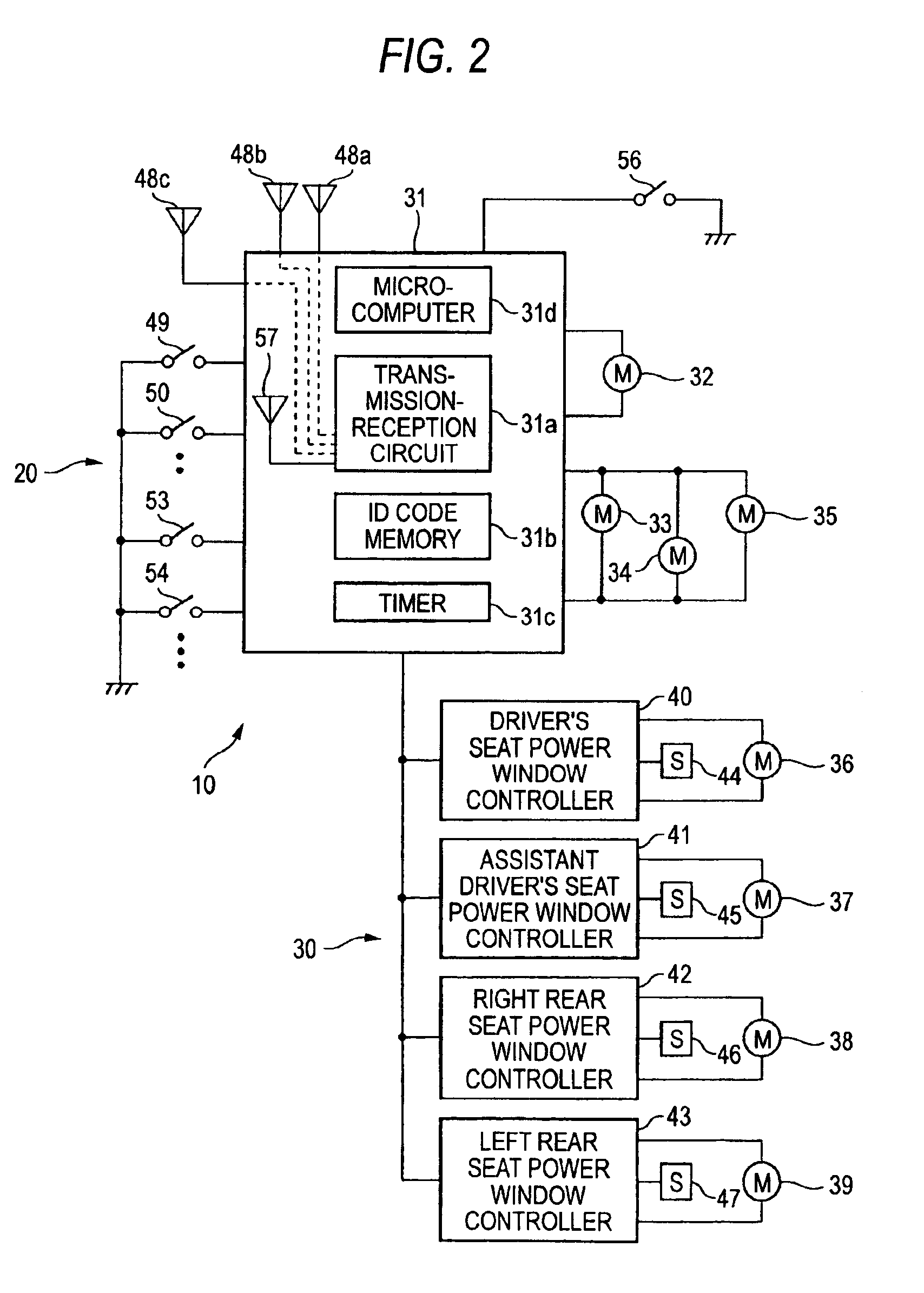
[0027]FIG. 1 is a circuit block diagram of a portable transmitter-receiver (hereinafter referred to as portable key) 6 as for an embodiment of the invention. FIG. 2 is a circuit block diagram of an on-vehicle device 10 including a transmitter-receiver controller (main controller) 20 mounted on a vehicle, and a peripheral circuit (sub-controller) 30.

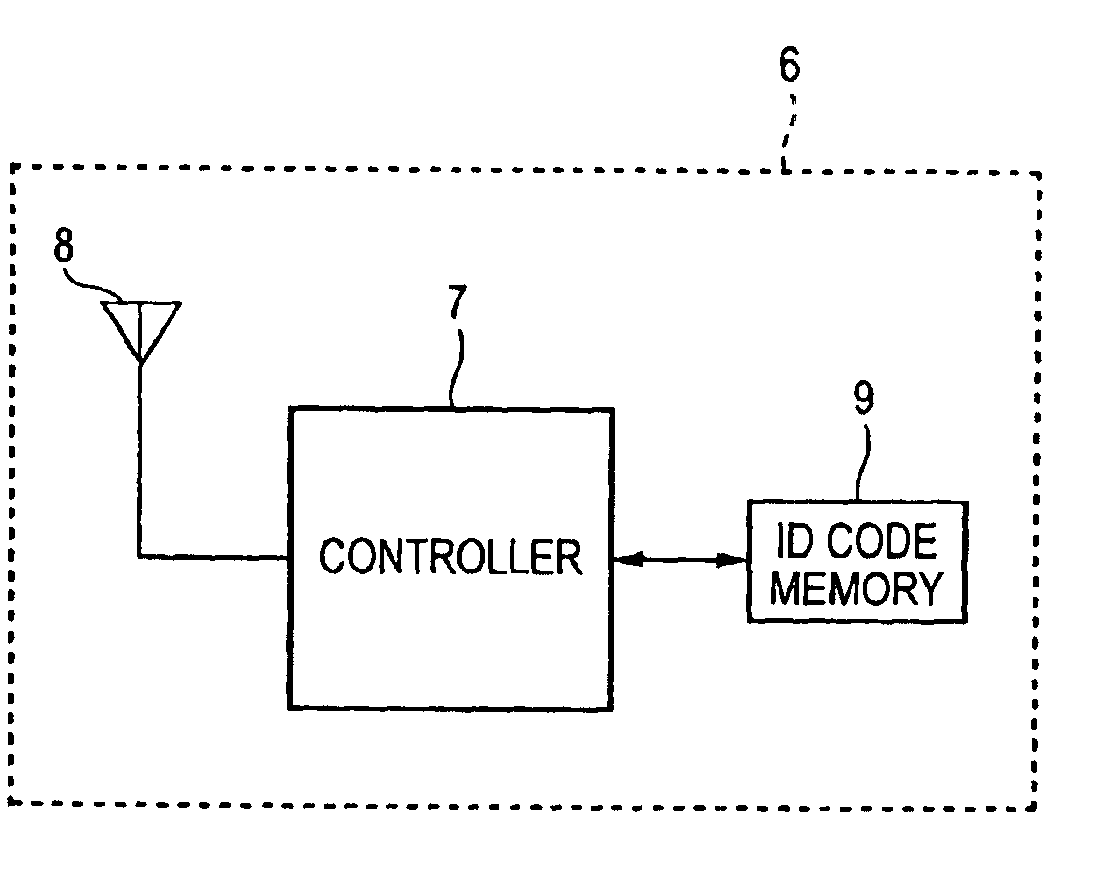
[0028]As shown in FIG. 1, the portable key 6 includes a controller 7 having a microcomputer, an antenna 8 and an ID code memory 9. The portable key 6 communicates with the transmitter-receiver controller 20 of the on-vehicle device 10 shown in FIG. 2 and does not include the operating switches 1a and 1b described in the related art.

[0029]The ID code memory 9, which is a nonvolatile memory in which an ID code set uniquely to each portable key is stored, is connected to the controller 7. The antenna 8 is also co...


PUM


Abstract

A wireless communication system for a vehicle, including: a portable transmitter-receiver adapted to communicate information wirelessly; a main controller mounted on the vehicle, the main controller adapted to communicate information wirelessly with the portable transmitter-receiver, to determine whether the portable transmitter-receiver is located within a communicatable range, and to output an enable signal when the portable transmitter-receiver is located within the communicatable range; a sub-controller mounted on the vehicle and connected to the main controller, the sub-controller adapted to enable-control of a vehicle mounted electronic device when the enable signal is input from the main controller.

Description

BACKGROUND OF THE INVENTION[0001]1. Field of the Invention[0002]The present invention relates to a wireless communication system for vehicles such as keyless entry system for remotely controlling an electric device mounted on the vehicle such as door locking / unlocking device and power window actuator, by checking on an ID code without using a key.[0003]2. Description of the Related Art[0004]In a related art, a wireless communication system for vehicles for remotely controlling an electric device mounted on the vehicle by checking on an ID code is disclosed in Japanese unexamined Patent publication JP-A-10-131569. The disclosure of the publication will be briefly described herein below.[0005]As shown in FIGS. 5 and 6, operating switches (a door locking switch 1a and a door unlocking switch 1b), a transmission circuit 2a, an ID code memory 2b, and an antenna 2c are provided at a grip section of a portable key 1. When either of the operating switches 1a and 1b is turned on, the transmi...

Claims


Application Information

Patent Timeline
Patent Type & Authority Patents(United States)
IPC IPC(8): G07C9/00E05F15/16B60J1/17B60J5/00E05F15/20E05B49/00
CPCG07C9/00309E05Y2900/55G07C2009/00793E05F15/76G07C2209/63E05F15/695G07C2209/08
Inventor NAGANO, TETSUJI
Owner CALSONIC KANSEI CORP
Why Eureka
Try Eureka