Gas-fired water heater

a water heater and gas-fired technology, applied in the field of gas-fired water heaters, can solve the problems of inability to achieve the required low values of co and nox concentration, inability to add additional combustion air, undesirable in regard to maintaining exhaust gas quality, etc., and achieve the effect of rapid and easy assembly, disassembly or exchang

Inactive Publication Date: 2005-09-20
ORKLI SCOOP
View PDF6 Cites 8 Cited by
  • Summary
  • Abstract
  • Description
  • Claims
  • Application Information

AI Technical Summary

Benefits of technology

[0013]It is an object of the present invention to provide a gas-fired water heater of the U.S.—water-heater type with a combustion chamber, which is constructed so that the gas burner can be rapidly and easily assembled, disassembled or exchanged during repair and maintenance procedures.
[0017]By the use of a burner mat with an outstandingly low pressure drop in a range of less than 5 Pa up to 45 Pa, according to the specific load (W / cm2) and perforations, sealing the combustion chamber from the environment is not necessary. The legally required low exhaust gas concentration for CO and NOx can be attained without sealing the combustion chamber in contrast to the state of the art because of the greatly reduced pressure drop. This has the advantage that the low exhaust gas concentrations in contrast to the state of the art are maintained even at higher operating loads, for example 40,000 BTU, 50,000 BTU and 60,000 BTU (British Thermal Units).
[0021]In addition the burner itself protects from a backfire of flames through the burner material into the combustion chamber, the so-called “flash back”. The quasi-flash-back protection is provided at low burner capacity by the lower pressure loss and the resulting great draw.
[0022]The elimination of expensive sealing of the combustion chamber makes a simplified burner construction, a sort of door structure for the burner, possible. The gas burner of the invention is insertable like a drawer into the combustion chamber and is releasably attached to the wall of the combustion chamber without sealing means. Because of that the entire gas burner can be disassembled rapidly for maintenance and the burner mat itself likewise, according to its structure, can be rapidly and easily exchanged. Also the problem of flame blocking or arresting is solved by means of this door structure. The gap between the door and the wall of the combustion chamber should be definitely constructed so that the flames cannot backfire. This can be achieved e.g. with suitable stamped nubs, knobs or burls.

Problems solved by technology

Intake of additional combustion air, also called secondary air, is not possible and undesirable in regard to maintaining exhaust gas quality, because the combustion chamber is sealed from the surroundings.
If additional combustion air could flow in, the required low values of CO and NOx concentration could not be attained.
However sealing the combustion chamber from the surrounding air is only accomplished with extra effort and is not economical.
The closed, completely sealed combustion chamber makes servicing and maintenance, and also construction, of the gas burner difficult.

Method used


Image

  • Gas-fired water heater
  • Gas-fired water heater
  • Gas-fired water heater

Examples


Embodiment Construction

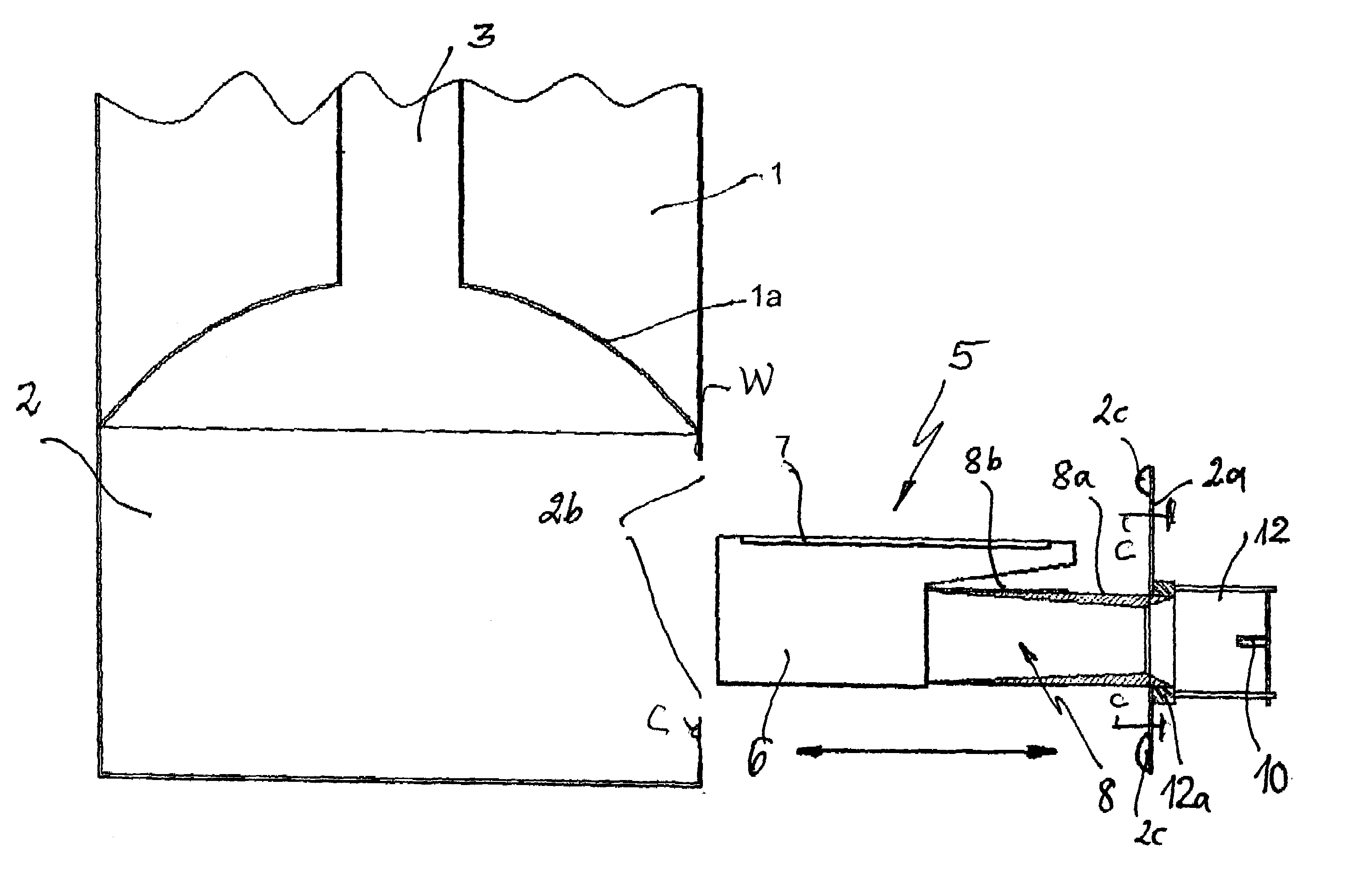
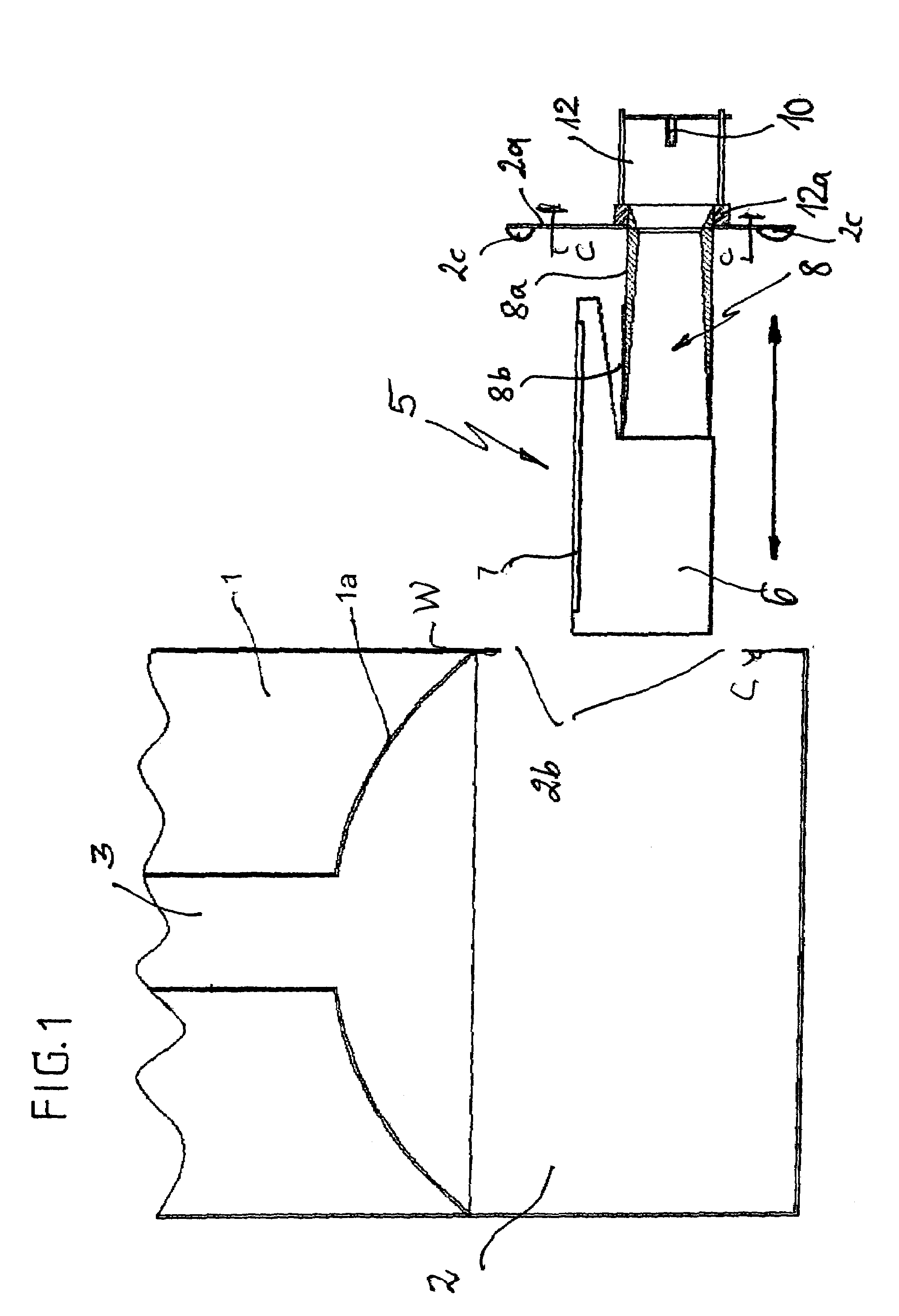
[0029]FIG. 1 shows a basic structure of the water heater according to the invention comprising a water tank 1, an exhaust gas flue 3 passing centrally through the water tank 1 and a curved cup-shaped lower wall 1a, under which the compartment-like combustion chamber 2 is located.

[0030]These parts of the structure of the water heater are known and needs no further detailed description.

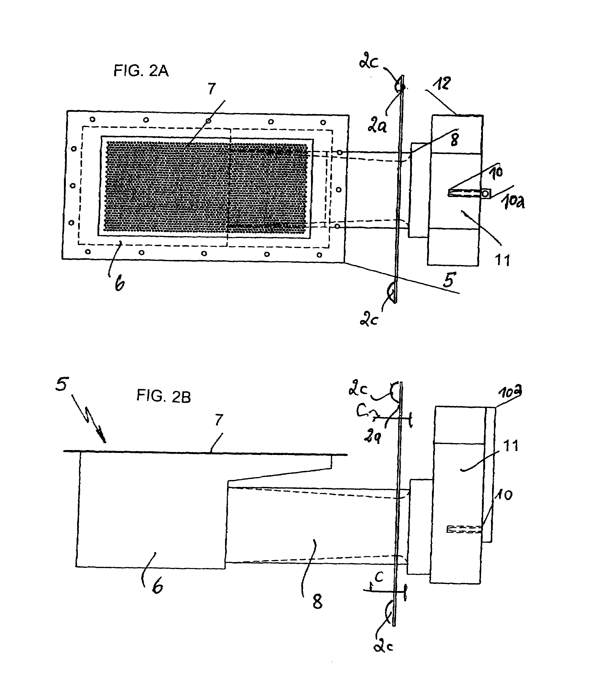
[0031]In contrast to the known structure the complete pre-mix burner 5 is not “so-to-speak” stationary within a completely sealed combustion chamber 2, but it is formed so that it can be pushed into and pulled out from the combustion chamber like a drawer. Also an opening 2b is formed in an outer wall W of the combustion chamber, which is closed by a wall section 2a mounted or attached to the burner 5 without expensive or difficult sealing elements. The wall section 2a has knobs, burls or nubs 2c, which provide a gap with a definite gap width (about 0.8 mm) and form a flame-blocking device (flame arrest...


PUM


Abstract

The water heater has an upright water tank (1), an exhaust flue (3) extending through the water tank, a combustion chamber (2) arranged under the water tank, an atmospheric gas burner (5) in the combustion chamber and a complete pre-mixing gas / air supply system with outside gas and air intakes. The gas burner has a burner mat (7) with a pressure drop less than 5 to up to 45 Pa. The combustion chamber (2) is provided with an opening (2b), which is not sealed, but enclosed in a flame-blocking manner. The gas burner (5) is attached to a wall section (2a), which is mounted releasably on the: combustion chamber wall (W) over opening (2b) so that a gap of predetermined width is formed between the wall section and wall (W), which prevents backfire of flames into the surroundings but admits secondary air.

Description

BACKGROUND OF THE INVENTION[0001]1. Field of the Invention[0002]The present invention relates to a gas-fired water heater, comprising an upright thermally insulated cylindrical water tank, a central exhaust flue extending axially through the water tank and a combustion chamber arranged under the exhaust flue, which has an atmospheric gas burner in it. The atmospheric gas burner has a flat burner mat and a complete pre-mixing gas / air supply system with a combustion-gas-single-barreled combustion gas nozzle, which has an intake for the combustion gas and combustion air arranged outside of the combustion chamber.[0003]2. Description of the Related Art[0004]Gas-fired water heaters are marketed in many different embodiments for different applications. They serve especially for supplying hot water in homes or houses. The so-called boiler for supplying hot water is a typical unit of this sort.[0005]The present invention relates to a special, gas-fired water heater, the so-called “water hea...

Claims


Application Information

Patent Timeline
Patent Type & Authority Patents(United States)
IPC IPC(8): F22B5/00F22B5/04F23C5/02F24H1/00F24H1/18F24H1/20F24H9/00F24H9/06F24H9/18
CPCF23C5/02F24H9/1836F23D2203/105F23D2212/103F24H1/205
Inventor HUBERT, STEFANFORBERICH, OLIVERGROEHL, ALEXANDERROELFSEMA, KLAASNEUBAUER, RAINER
Owner ORKLI SCOOP
Why Eureka
Try Eureka