EGR control apparatus for engine

a control apparatus and engine technology, applied in the direction of electric control, machines/engines, combustion air/fuel air treatment, etc., can solve the problems of insufficient nox reduction, inability to exert a sufficient egr effect of conventional egr system, and inability to disclose any measures to be taken in the prior art, etc., to achieve heat resistance, durability and reliability.

Inactive Publication Date: 2005-09-20
MAZDA MOTOR CORP
View PDF19 Cites 71 Cited by
  • Summary
  • Abstract
  • Description
  • Claims
  • Application Information

AI Technical Summary

Benefits of technology

[0008]In view of the foregoing, it is an object of the invention to provide an EGR system which makes it possible to introduce EGR gas into combustion chambers regardless of operating conditions of an engine even under high-load conditions. More particularly, it is an object of the invention to achieve heat resistance, durability and reliability of a pressure controller disposed in an EGR passage.

Problems solved by technology

In the EGR system thus constructed, it is difficult to maintain a sufficient amount of recirculated EGR gas under high-load conditions due to a reduction in the difference between the exhaust and intake pressures.
A resulting problem is that the conventional EGR system can not exert a sufficient EGR effect, or sufficiently reduce the amount of NOx, under high-load conditions.
Nevertheless, the prior art does not disclose any measures to be taken to achieve this requirement.

Method used


Image

  • EGR control apparatus for engine
  • EGR control apparatus for engine
  • EGR control apparatus for engine

Examples


Embodiment Construction

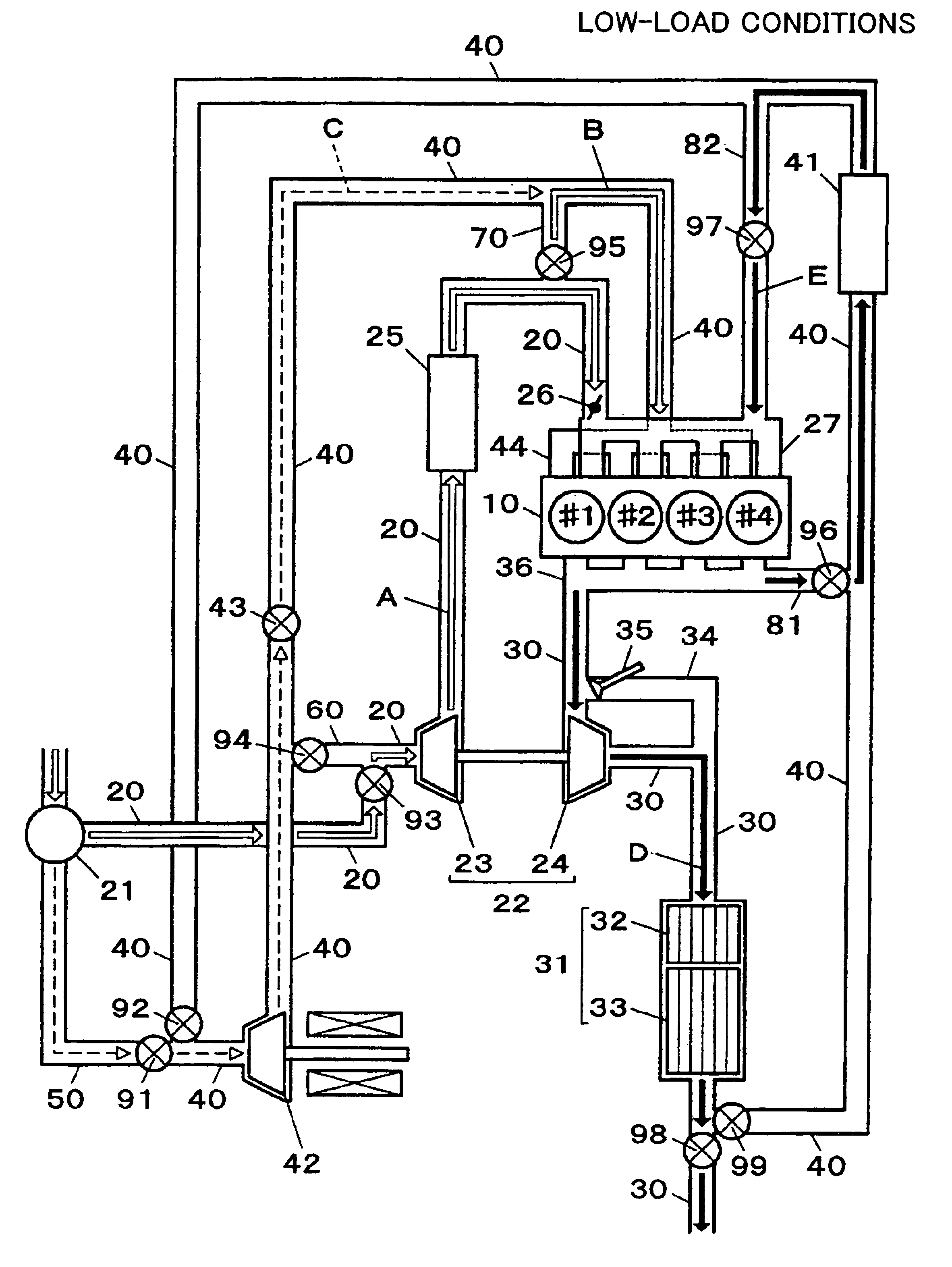
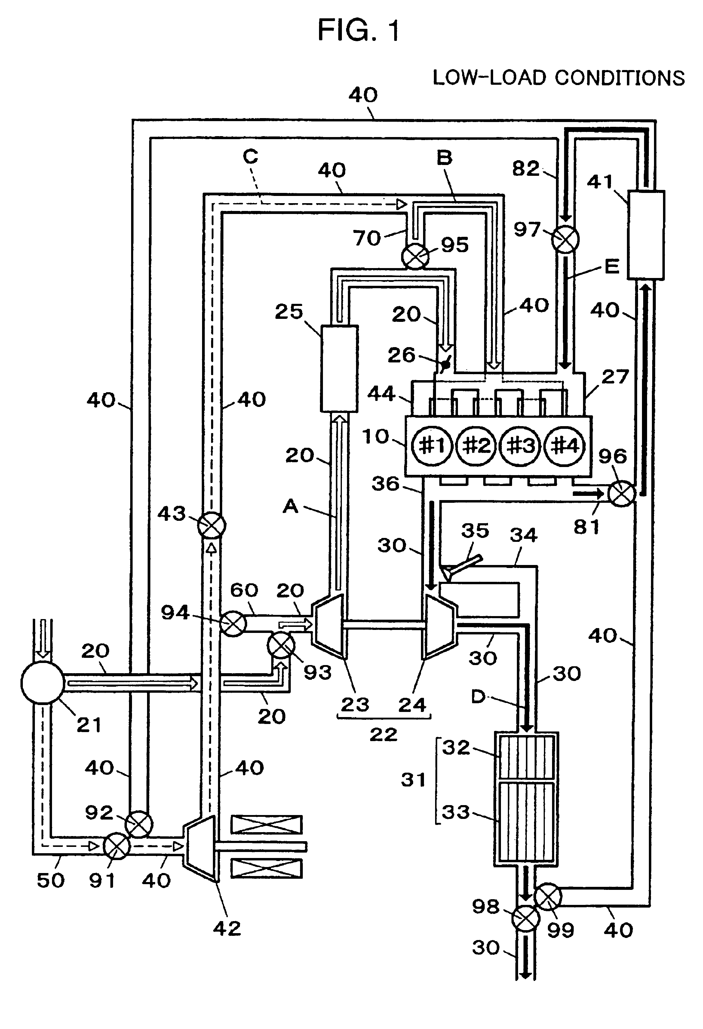
[0020]A preferred embodiment of the present invention is described, by way of example, with reference to a four-cylinder diesel engine 10 employing an EGR system shown in FIG. 1. The engine 10 has an intake passage 20, an exhaust passage 30 and an EGR passage 40. There are disposed an air cleaner 21, a compressor 23 of a supercharger 22, an intercooler 25 and an intake air throttle valve 26 in the intake passage 20 from an upstream side thereof along the direction of fluid flow. A downstream end of the intake passage 20 is connected to an engine body 10 through an intake manifold 27.

[0021]On the other hand, there are disposed a turbine 24 of the supercharger 22 and an emission control device 31 in the exhaust passage 30 from an upstream side thereof along the direction of fluid flow. Driven by the turbine 24 disposed in the exhaust passage 30, the compressor 23 disposed in the intake passage 20 supercharges the engine 10 by compressing intake air flowing through the intake passage 2...


PUM


Abstract

According to the invention, an EGR control apparatus of an engine includes intake ports to which an intake passage is connected, the intake ports opening into each combustion chamber of the engine, an EGR port to which an EGR passage branching out from an exhaust passage is connected, the EGR port opening into each combustion chamber of the engine, an electrically-operated compressor disposed in the EGR passage for regulating pressure at which EGR gas is introduced into each combustion chamber, and an EGR control valve disposed in the EGR passage at a point downstream of the electrically-operated compressor for controlling the amount of EGR gas introduced into each combustion chamber. The EGR passage branches out from the exhaust passage at a point downstream of an emission control device disposed in the exhaust passage.

Description

BACKGROUND OF THE INVENTION[0001]1. Field of the Invention[0002]The present invention relates to an exhaust gas recirculation (EGR) control apparatus of an engine designed to introduce exhaust gas, or EGR gas, back to a combustion chamber. More particularly, the invention pertains to an EGR control apparatus capable of introducing EGR gas into a combustion chamber even under high-load conditions.[0003]2. Description of the Related Art[0004]Conventionally, EGR systems are widely used to reduce the amount of nitrogen oxides (NOx) contained in exhaust gases by reducing combustion temperature in combustion chambers of an engine. Generally, the EGR system includes an EGR passage connecting an exhaust passage to an intake passage to recirculate part of the exhaust gas from the exhaust passage to the intake passage and into a combustion chamber. The amount of EGR gas recirculated through the EGR passage is regulated by an EGR control valve disposed in the EGR passage according to operating...

Claims


Application Information

Patent Timeline
Patent Type & Authority Patents(United States)
IPC IPC(8): F02B31/08F02B31/00F02M25/07F02M35/104F02M35/108F02M35/10F02B37/00F02B33/34F02B37/18F02D21/08F02D41/00
CPCF02B31/085F02M25/0707F02M25/0709F02M25/071F02M25/0711F02M25/0727F02M25/0735F02M25/0739F02M25/0742F02M25/0743F02M25/0744F02M25/0747F02M25/0748F02M25/0777F02M35/10157F02M35/10222F02M35/108F02M35/1085F02B33/34F02B37/18F02D41/0065F02M25/0713F02M25/0731F02M25/0738F02M35/1038F02M35/10386F02M2025/0769Y02T10/146Y02T10/144F02B37/04F02M26/07F02M2026/009F02M26/57F02M26/05F02M26/06F02M26/08F02M26/10F02M26/23F02M26/28F02M26/30F02M26/33F02M26/34F02M26/36F02M26/37F02M26/38F02M26/41F02M26/42F02M35/112Y02T10/12
Inventor NAKAI, EIJIMATSUMOTO, YOSHIYUKI
Owner MAZDA MOTOR CORP
Why Eureka
Try Eureka