Determination of leak and respiratory airflow

a leakage and airflow technology, applied in the direction of valve operating means/release devices, catheters, diagnostic recording/measuring, etc., can solve the problems of leakage between the mask and the subject, incorrect calculation of respiratory airflow, and only correct known methods

Inactive Publication Date: 2005-09-20
RESMED LTD
View PDF36 Cites 50 Cited by
  • Summary
  • Abstract
  • Description
  • Claims
  • Application Information

AI Technical Summary

Benefits of technology

[0037]Embodiments of the invention provide advantages over the prior art. There is no need to know when transitions between respiratory pleases occurs. The independence from knowledge of th

Problems solved by technology

Leaks between the mask and the subject are unavoidable.
The known method is only correct if the pressure at the mask is constant.
If the mask pressure varies with time (for example, in the case of a ventilator), assumption (i) above will be invalid, and the calculated respiratory airflow will therefore be incorrect.
In general, it can be diffi

Method used


Image

  • Determination of leak and respiratory airflow
  • Determination of leak and respiratory airflow
  • Determination of leak and respiratory airflow

Examples


Embodiment Construction

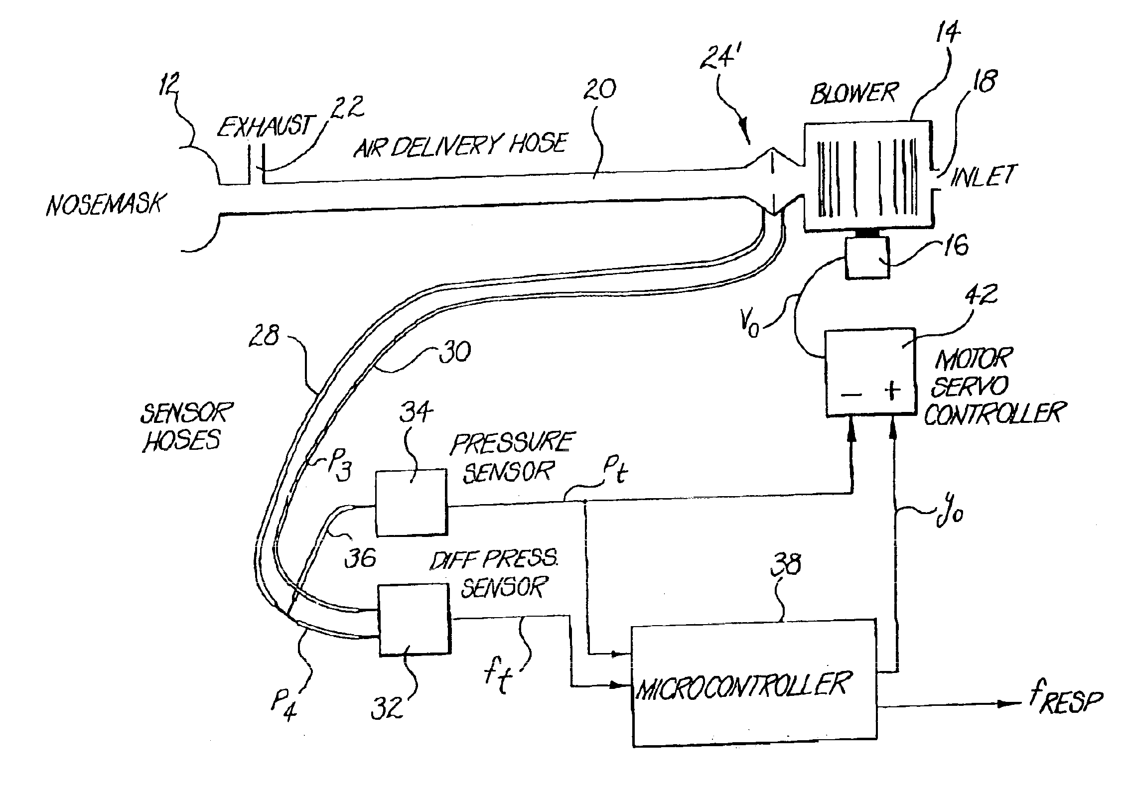
[0049]FIG. 2a shows mechanical ventilation apparatus 10 embodying the invention.

[0050]The subject / patient wears a nose mask 12 of any known type. The subject equally could wear a face mask or nasal prongs / pillows, or alternatively have an endotracheal tube or tracheostomy tube in place. A turbine / blower 14, operated by a mechanically coupled electrical motor 16, receives air or breathable gas at an inlet 18 thereof, and supplies the breathable gas at a delivery pressure to a delivery tube / hose 20 having connection at the other end thereof with the nose mask 12. Breathable gas thus is provided to the subject's airway for the purpose of providing assisted respiration, with the subject's expired breath passing to atmosphere by an exhaust 22 in the delivery tube 20, typically located proximate to the mask 12.

[0051]A pneumotachograph 24 is placed in the deliver tube 20 between the mask; 12 and the exhaust 22 to provide two pressure signals, P2 and P1, across the pneumotachograph, each pa...


PUM


Abstract

Methods and apparatus for determining leak and respiratory airflow are disclosed. A pressure sensor (34) and a differential pressure sensor (32) have connection with a pneumotach (24) to derive instantaneous mask pressure and airflow respectively. A microcontroller (38) estimates a non-linear conductance of any leak path occurring at a mask (12) as being the low pass filtered instantaneous airflow divided by the low pass filtered square root of the instantaneous pressure. The instantaneous leak flow is then the conductance multiplied by the square root of the instantaneous pressure, and the respiratory airflow is calculated as being the instantaneous airflow minus the instantaneous leak flow. The time constants for the low pass filtering performed by the microcontroller (38) can be dynamically adjusted dependent upon sudden changes in the instantaneous leak flow.

Description

[0001]This application is a continuation of application Ser. No. 09 / 902,011 filed on Jul. 10, 2001, now U.S. Pat. No. 6,659,101, which is a continuation of application Ser. No. 09 / 525,042 filed Mar. 14, 2000, now U.S. Pat. No. 6,279,569, which is a continuation of application Ser. No. 08 / 911,513 filed Aug. 14, 1997, now U.S. Pat. No. 6,152,129.FIELD OF THE INVENTION[0002]The invention relates to methods and apparatus for the determination of leakage airflow and true respiratory airflow, particularly during mechanical ventilation.[0003]The airflow determination can be for a subject who is either spontaneously or non-spontaneously breathing, or moves between these breathing states. The invention is especially suitable for, but riot limited to, normally conscious and spontaneously breathing human subjects requiring long term ventilatory assistance, particularly during sleep.BACKGROUND OF THE INVENTION[0004]In this specification any reference to a “mask” is to be understood as including...

Claims


Application Information

Patent Timeline
IPC IPC(8): A61M16/00
CPCA61M16/00A61M16/0057A61M16/0003A61M16/0069A61M2016/0021A61M2016/0036A61M2205/15A61M2016/0027A61M2016/0033A61M16/024
Inventor BERTHON-JONES, MICHAEL
Owner RESMED LTD
Why Eureka
Try Eureka