Non-rotating cement wiper plugs

a technology of cement wiper plugs and wipers, which is applied in the direction of fluid removal, sealing/packing, borehole/well accessories, etc., can solve the problems of one or both wiper plugs, spin or rotate, and problems such as the wiper plugs

Inactive Publication Date: 2005-09-20
MIKOLAJCZYK RAYMOND F
View PDF3 Cites 19 Cited by
  • Summary
  • Abstract
  • Description
  • Claims
  • Application Information

AI Technical Summary

Problems solved by technology

Problems arise where drilling is to continue beyond the casing string depth.
A potential problem is that one or both of the wiper plugs, which as described earlier have “landed” on the float collar (or float shoe, if no float collar has been run), spin or rotate along with the rotary drill bit, rather than remain rotationally locked in place for easy drillup.
Obviously, as long as the plug or plugs spin along with the bit, little or no progress in drilling therethrough can be made, and in some instances much time, and consequently money, is lost.
The problem, then, is how to keep the plugs from spinning beneath the drill bit during the drillout procedure.
However, a common drawback to the prior art apparatus is the requirement of matched float equipment and cement wiper plugs and / or additional labor and equipment in order to achieve the rotationally locking functions.
While the cementing function can be carried out with whether or not the float equipment and plugs have some sort of matching, meshing teeth or other profiles, it can be readily seen that without the matching aspect, the rotationally locking situation will not be achieved.
The requirement of “matched” float equipment and plugs gives rise to increased cost, and the ever-present possibility of mismatched equipment being used in the hectic nature of oilfield work.
Yet another limitation of prior art, matched plugs and float equipment is the possibility of a build-up of debris on the matching or mating components, such as teeth, of the cementing equipment, or a fluid flow-back through the float equipment which would separate the plug from the float equipment and therefore unseat the meshing lock profiles.
Such a build-up of debris or fluid flow-back often impedes the mating of the matching components, consequently the cement wiper plugs do not rotationally lock in place.
A drawback to this apparatus is binding of the drill bit when the assembly is drilled up, and the ever-present possibility of an incorrect non-rotating sleeve installation.

Method used


Image

  • Non-rotating cement wiper plugs
  • Non-rotating cement wiper plugs
  • Non-rotating cement wiper plugs

Examples


Embodiment Construction

[0022]While the present invention may be made in a number of different embodiments, with reference to the drawings some of the presently preferred embodiments will be described. Those skilled in the relevant art will recognize that departures may be made from the described embodiments, while still falling within the scope of the present invention.

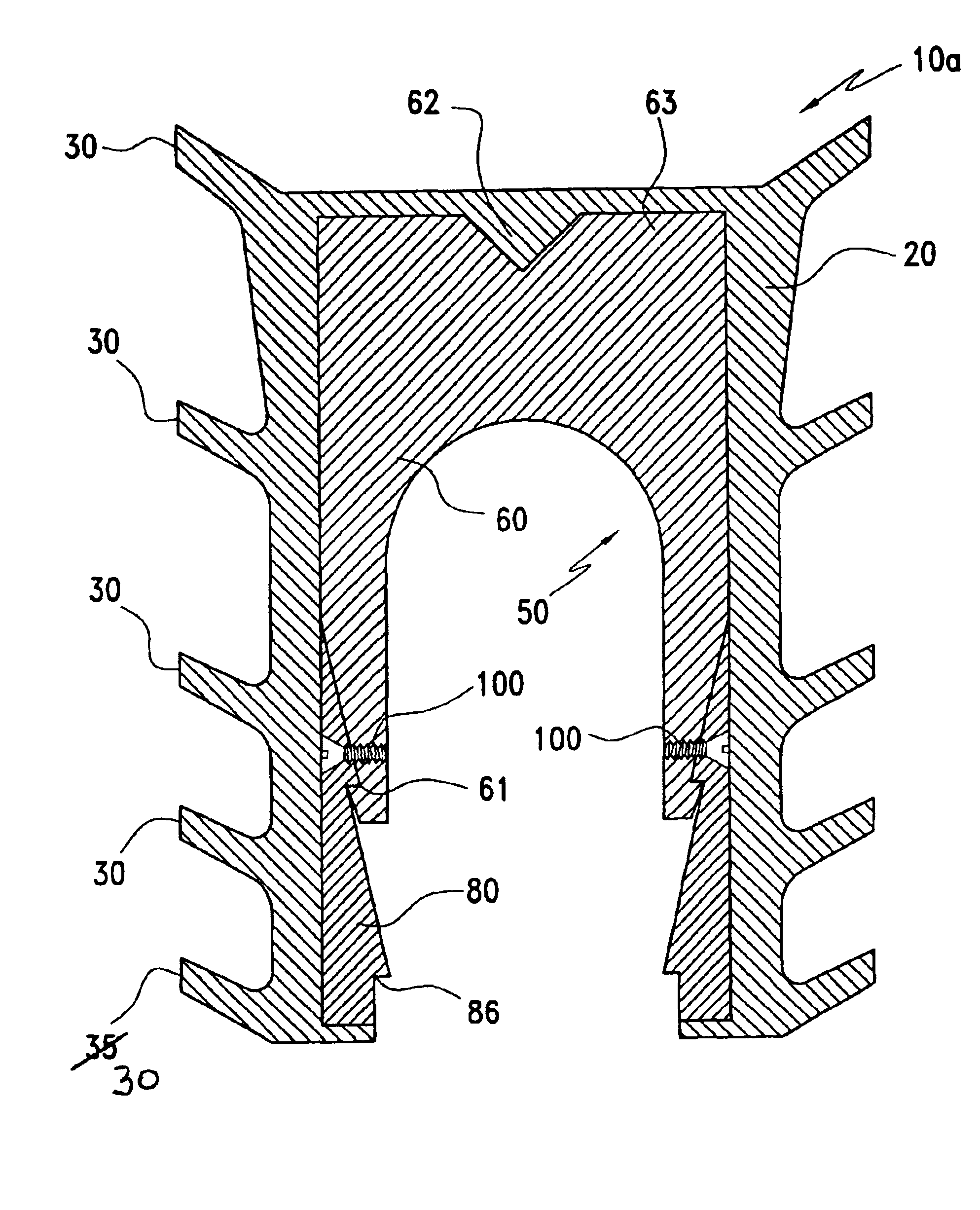
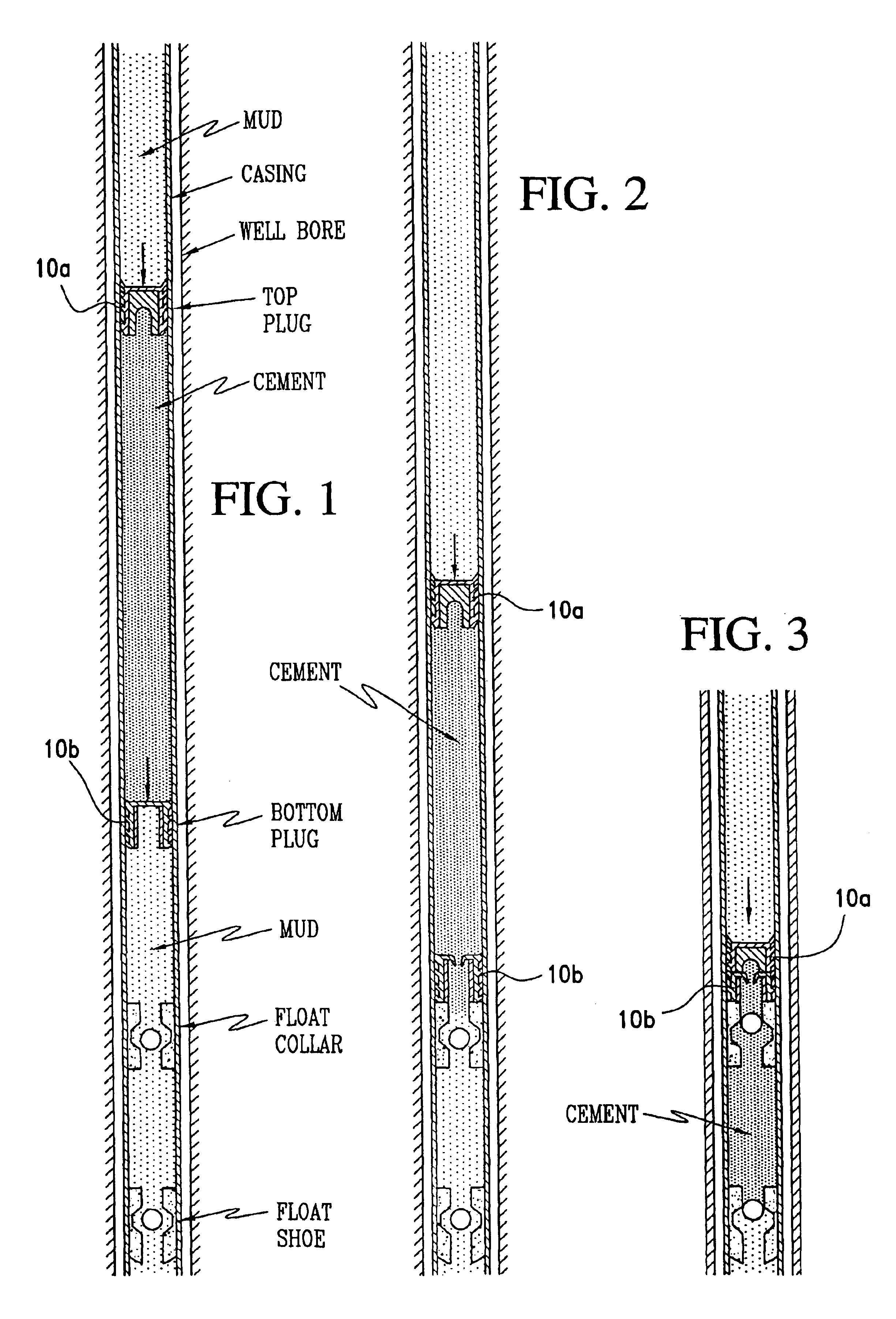
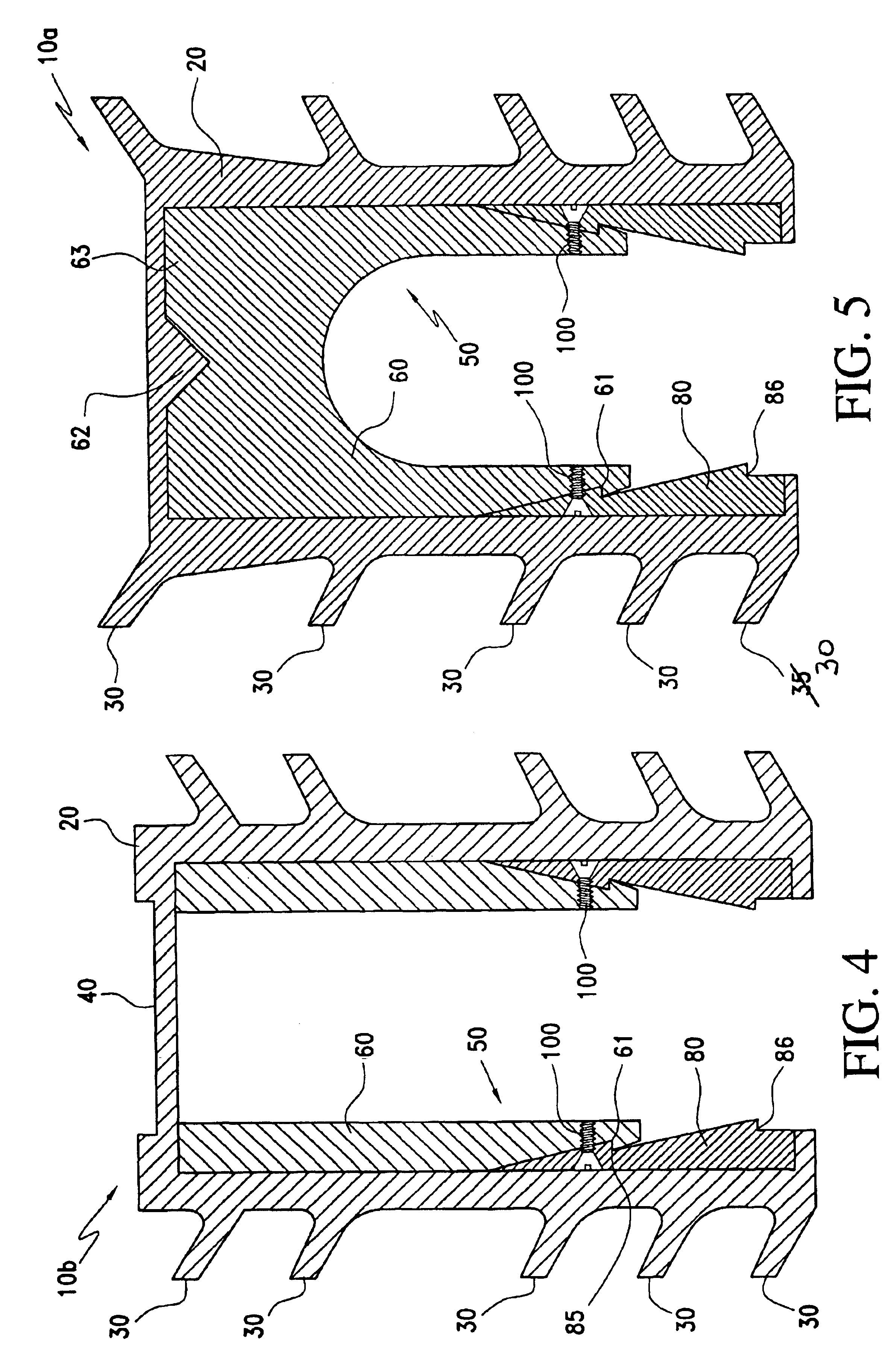
[0023]FIGS. 1-3 set forth a typical cement pumping sequence, with the cementing plugs of the present invention. In FIG. 1, a casing string is shown within an earthen borehole. A float shoe is at the bottom of the casing string, and a float collar is installed a short distance uphole in the casing string (typically one to three casing joints up). Both the float shoe and float collar have one-way or check valves therein, which permit fluid flow downwardly through them, but not in the opposite direction. In FIG. 1, a bottom cement wiper plug and a top cement wiper plug (at times referred to hereafter as simply “bottom plug” and “top plug”) are...


PUM


Abstract

A non-rotating cement wiper plug has an insert, with inner and outer telescoping sleeves, within a resilient outer body. The outer body has annular fins which bear against a casing wall. The inner sleeve has a tapering nose within a tapered cavity in the outer sleeve. Slots in the outer sleeve form a plurality of segments. The inner and outer sleeves are preferably of a frangible material. When the plug is pumped down and lodges against downhole float equipment, pump pressure compresses the plug, forces the inner sleeve down within the outer sleeve, forces the segments radially outward, and fractures or separates the outer sleeve segments. The outer body is forced against the casing wall so tightly that it cannot rotate in response to the forces from a rotary drill bit. Lock surfaces on the inner and outer sleeves lock them together and maintain the outer body in its forced-outwardly position.

Description

BACKGROUND[0001]1. Field of Invention[0002]This invention relates to equipment used in connection with the cementing of casing strings in earthen boreholes. More particularly, this invention relates to wiper plugs used in the cementing process.[0003]2. Description of Prior Art[0004]In the field of drilling earthen boreholes or “wells,” particularly wells for oil and gas production, each section of open hole (that is, the hole drilled in the earth) is generally cased off by a length of iron or steel casing placed into the borehole. This length of casing is commonly referred to as a “casing string.” Some of the purposes of casing are to maintain the structure of the sediment surrounding the hole, as well as to prevent contamination of any nearby oil or water structure. Other purposes relate to the containment of drilling fluids needed to control subsurface pressures. At the very bottom of the casing string is usually a “float shoe,” and one or more (but generally no more than two or t...

Claims


Application Information

Patent Timeline
Patent Type & Authority Patents(United States)
IPC IPC(8): E21B33/08E21B33/02E21B33/13E21B33/16
CPCE21B33/08E21B33/16E21B33/167
Inventor MIKOLAJCZYK, RAYMOND F.
Owner MIKOLAJCZYK RAYMOND F
Why Eureka
Try Eureka