Method and system to mitigate pump noise in a direct injection, spark ignition engine

a technology of direct injection and spark ignition, which is applied in the direction of fuel injecting pumps, electric control, machines/engines, etc., can solve the problems of pump, fitting, or other fuel system components failing, and the noise of clicking is noticeable, so as to improve the metering accuracy of the fuel injector, increase the pulse width of the injector, and high pressure fuel

Inactive Publication Date: 2008-05-20
FORD GLOBAL TECH LLC
View PDF19 Cites 27 Cited by
  • Summary
  • Abstract
  • Description
  • Claims
  • Application Information

AI Technical Summary

Benefits of technology

[0010]An advantage of the present invention is that by turning off the solenoid valve, the undesirable noise of the solenoid valve actuation, during engine idle, is overcome. Additionally, at low-torque engine operating conditions, at which conditions the electronic control unit demands a low quantity of fuel, when operating at high pressure, the fuel injectors are commanded to open for a short duration to provide such low quantity of fuel. The accuracy at which the injectors can provide high pressure fuel is less than desired. But, when operating at low pressure, the increased injector pulse width allows improved metering accuracy of the fuel injectors. Not only is combustion stability improved by increased accuracy in the in-cylinder air-fuel ratio, but also the emissions from the engine are reduced and the exhaust catalyst efficiency is improved.
[0011]In an alternative embodiment, a return line from the fuel rail to the tank is provided. Although the cost advantage of avoiding a return line and pressure regulator is not achieved in such embodiment

Problems solved by technology

However, at idle, when the engine is at its quietest and there is no road and limited wind noise, the clicking noise is noticeable and can be a source of customer concern or dissatisfaction.
Eventually,

Method used


Image

  • Method and system to mitigate pump noise in a direct injection, spark ignition engine
  • Method and system to mitigate pump noise in a direct injection, spark ignition engine
  • Method and system to mitigate pump noise in a direct injection, spark ignition engine

Examples


Embodiment Construction

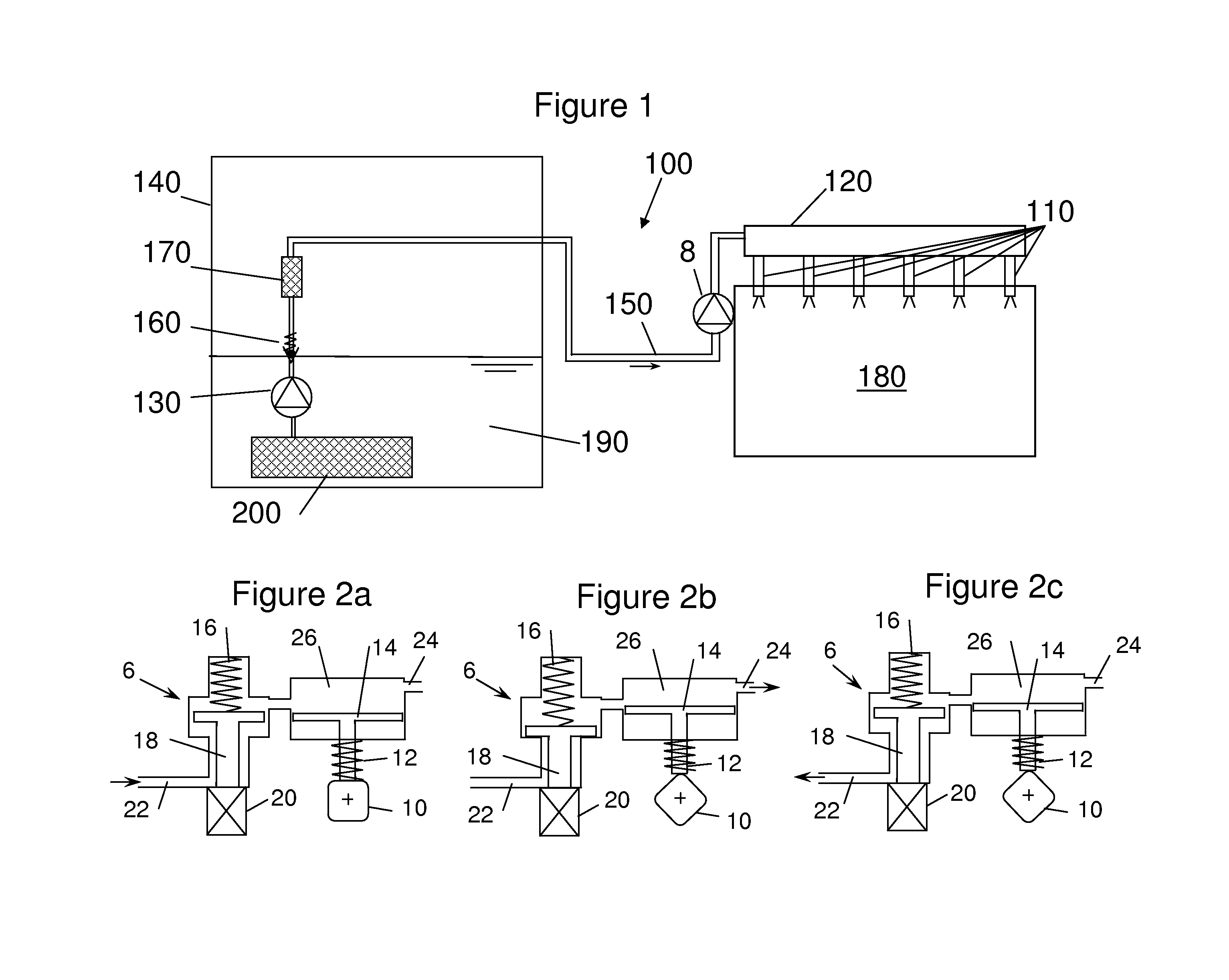
[0018]A schematic of a high pressure fuel system 100 for a direct injection engine is shown in FIG. 1. A low pressure fuel pump 130 is disposed in a fuel tank 140. Fuel 190 passes through filter 200 prior to entering pump 130. A check valve 160 is disposed in the fuel line prior to filter 170. Low pressure fuel line 150 supplies fuel to high pressure pump 8. In one embodiment, high pressure pump 8 is driven off engine 180. Alternatively, pump 8 is driven by an electric motor. High pressure pump 8 supplies fuel to fuel rail 120 which is connected to high pressure fuel injectors 110. Injectors 100 spray fuel directly into engine cylinders within engine 180.

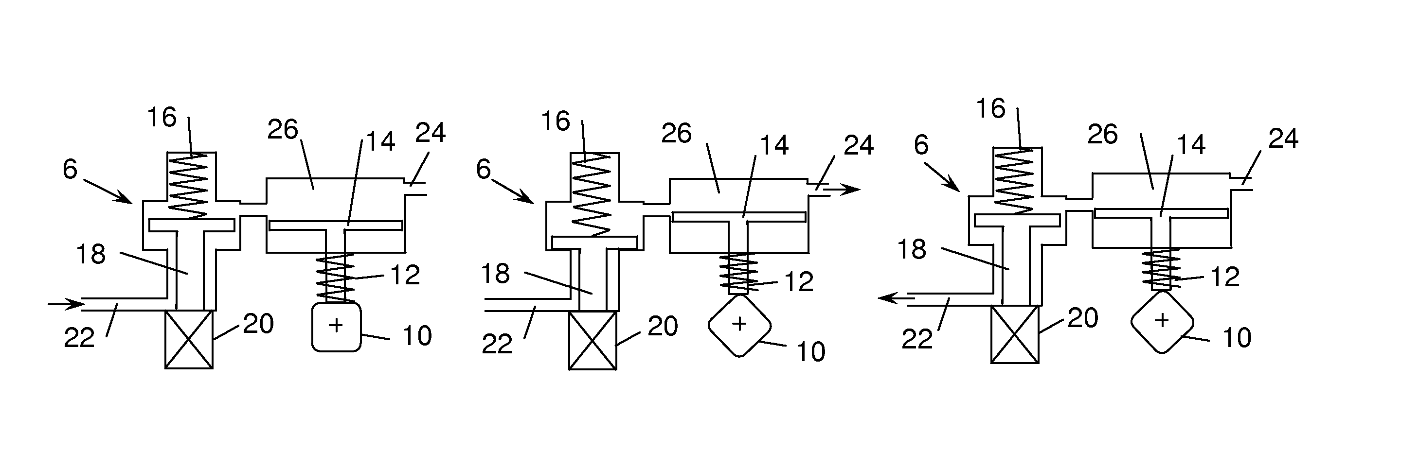
[0019]High pressure pump 8, in FIGS. 2a-2c, has an inlet 22 from the low pressure pump and an outlet 24 that feeds the high pressure fuel rail. The fuel inlet is controlled by a solenoid valve 6, which has an armature 18, a coil 20, and a spring 16. In FIGS. 2a and 2c, solenoid valve 6 is shown in its normally open position. In FIG....


PUM


Abstract

A method and system for controlling a fuel pressurizing system in a direct-injection, spark-ignition engine is disclosed such that the ticking sound of a solenoid valve in the high pressure pump is disabled at certain engine operating conditions. The fuel pressurizing system includes two pumps in series: a low pressure lift pump and a high pressure pump. Based on an engine operating parameter (speed, load, temperature, fuel delivery rate, as examples) the high pressure fuel pump is disabled when the engine operating parameter is below a threshold. The disablement of the pump is accomplished by turning off the normally-open solenoid valve on the inlet side of the high pressure pump, particularly at low speed and/or low torque conditions, e.g., idle, when the ticking of the injector is particularly noticeable. When the pump is disabled, fuel is supplied to the fuel injectors at lift pump pressure.

Description

FIELD OF THE INVENTION[0001]A method and system for controlling a fuel pressurizing system in a direct-injection, spark-ignition engine is disclosed. The fuel pressurizing system includes two pumps in series: a low pressure lift pump and a high pressure pump.BACKGROUND[0002]Direct-injection, spark-ignition engines typically operate with injection pressures up to 150 bar. To obtain such a high pressure, it is common to employ two pumps in series: a low pressure, electrically-operated pump bringing the pressure to 3 to 7 bar feeding a high pressure pump. The high pressure pump can be electrically, hydraulically, or mechanically operated. Mechanical pumps tend to predominate as they are more efficient than electric pumps and less complex than hydraulic pumps. To provide variable control of a mechanical pump, it is known to install a solenoid valve in the pump which can be opened and closed during the pump plunger's travel. When the solenoid valve is open, the pump plunger merely pumps ...

Claims


Application Information

Patent Timeline
IPC IPC(8): F02M69/54F02M69/52
CPCF02D41/3005F02D41/3845F02M37/10F02M59/366F02M63/0225F02M63/023F02M63/028F02M69/52F02M69/54F02B2075/125F02M59/102F02M2200/09Y02T10/123Y02T10/12
Inventor KRENGEL, ERICBESHAY, MANSOURHOFFMAN, DEANNA
Owner FORD GLOBAL TECH LLC
Why Eureka
Try Eureka