Rotating packed bed device with function of regulating and controlling axial liquid distribution

A high-gravity rotating bed and liquid distribution technology, applied in the field of high gravity, can solve problems such as uneven liquid distribution, weakened mass transfer effect, and insufficient utilization of rotor packing, so as to improve mass transfer efficiency and strengthen the gas-liquid mass transfer process , the effect of improving the utilization rate

Active Publication Date: 2011-11-23
BEIJING UNIV OF CHEM TECH
View PDF6 Cites 24 Cited by
  • Summary
  • Abstract
  • Description
  • Claims
  • Application Information

AI Technical Summary

Problems solved by technology

When the liquid flows to the rotor of the next stage, the liquid flows completely by gravity from the edge of the liquid collecting plate in the inner chamber of the upper layer to the inner wall of the rotor rotating at high speed in the next stage, resulting in uneven distribution of the liquid in the rotor packing layer
As a result of uneven distribution of liquid in the axial direction of the next stage rotor, the rotor packing will be underutilized and the mass transfer effect will be weakened.

Method used


Image

  • Rotating packed bed device with function of regulating and controlling axial liquid distribution
  • Rotating packed bed device with function of regulating and controlling axial liquid distribution
  • Rotating packed bed device with function of regulating and controlling axial liquid distribution

Examples


Embodiment 1

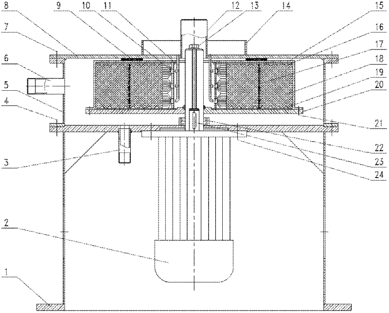
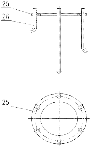
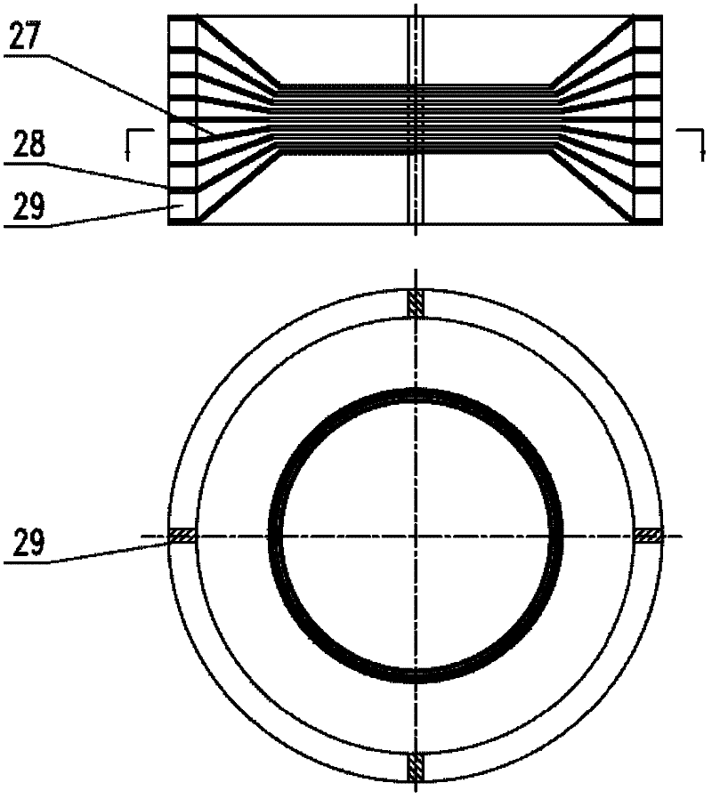
[0025] Such as figure 1 In the single-stage supergravity rotary bed device shown, in the airtight cavity 5 , the shaft of the motor 2 and the turntable 20 are fixed together with bolts 13 , and the motor 2 and the base 1 are fixed together with bolts 24 . The shaft of the motor 2 transmits torque to the shaft of the turntable 20 through the key 23, so that the rotor fixed on the turntable 20 rotates. The rotating bed rotor includes a packing gland 15, a packing core barrel 16, and a point-surface liquid distributor 10 (the schematic diagram is shown in image 3 , the inner part of the distributor is composed of 5 annular cone plates 27 with angles of 0°, 10°, 20°, 30°, and 40°, and a horizontal annular plate 28 is welded on the outside of the annular cone plate. Support plate 29 between plates 28), split cylinder liquid redistributor 17 (the schematic diagram is shown in Figure 4), the upper end surface and the lower end surface of the packing core barrel are provided with ...

Embodiment 2-25

[0030] The process flow and steps are the same as in Example 1, and the process conditions and operating conditions of each embodiment and the corresponding experimental results are shown in Table 1.

[0031] Process conditions and experimental results of each embodiment of table 1

[0032]

Embodiment 26

[0034] Schematic diagram of the structure of the high-gravity two-stage counter-current rotating bed of the present invention is as follows Figure 7 As shown, its structure is the same as figure 1 The structure is basically similar. Liquid flows from the reservoir 48 into the conduit liquid distributor 53 into the point surface liquid distributor 52 . The point surface liquid distributor 52 forces the liquid to distribute evenly in the axial direction of the packing. Under the action of centrifugal force, the liquid passes through the filler 51 and the split-cylindrical liquid redistributor 50, and then is sprayed out from the rotor, and finally is collected by the inner cavity and flows to the next rotor. In the next layer of rotor, the liquid goes through the same process, first flows into the duct type liquid distributor 46, passes through the point surface type liquid distributor 45, packing 42, split cylinder type liquid redistributor 43, and finally flows out from the...


PUM


Abstract

The invention discloses a rotating packed bed device with the function of regulating and controlling axial liquid distribution, and belongs to the technical field of supergravity. The device comprises a closed shell; the center of the shell is provided with a rotating shaft which runs through various shell sections; and a packing layer is arranged in a rotor. The axial uniform distribution of liquid can be realized by regulating and controlling the liquid by internal members such as a honeycomb duct type liquid distributor, a point-plane type liquid distributor, a split cylinder type liquid redistributor, a triangular conical ring and the like under the condition of no pump pressure, so that packing in the rotor is fully utilized, the mass transfer effect is strengthened, and the mass transfer efficiency can be improved by 60 to 70 percent. The internal members for regulating and controlling the axial distribution of the liquid can be used on a single-stage or multi-stage rotating bed, particularly rotors of a multi-stage countercurrent rotating bed except a first-stage rotor.

Description

technical field [0001] The invention relates to a high-gravity rotating bed device capable of regulating and controlling the axial liquid distribution, and specifically relates to some new internal components for improving the axial liquid distribution of the rotor, which can be applied to the high-gravity rotating packed bed of a single-stage or multi-stage rotor, and belongs to the super-gravity The field of gravity technology. Background technique [0002] In traditional gas-liquid mass transfer equipment such as absorption or rectification, the liquid is evenly sprayed on the top of the packing from the top of the tower through the liquid distributor, and the gas is sent from the bottom of the tower, flows through the gap of the packing, and countercurrently flows with the liquid in the packing layer. Contact for mass transfer. The uniform distribution of the gas-liquid two-phase in the packing layer greatly affects the effect of mass transfer. To this end, the researc...

Claims


Application Information

Patent Timeline
Patent Type & Authority Applications(China)
IPC IPC(8): B01D3/30B01D53/18B01J19/18
Inventor 陈建峰罗勇初广文邹海魁
Owner BEIJING UNIV OF CHEM TECH
Why Eureka
Try Eureka