Hydraulic riding trowels with automatic load sensing

a technology of automatic load sensing and riding trowels, which is applied in the direction of roads, construction, buildings, etc., can solve the problems of difficult steering and control of devices, new problems in the art, and the drive train of trowels, and achieve the effect of facilitating automatic control

Active Publication Date: 2011-09-15
ALLEN ENG
View PDF84 Cites 24 Cited by
  • Summary
  • Abstract
  • Description
  • Claims
  • Application Information

AI Technical Summary

Benefits of technology

[0046]This invention provides improved, high power, hydraulically-driven riding trowels equipped with a hydraulic unloader valve system for controlling the hydraulic pump or pumps driving the rotor drive motors. A hydraulic feedback circuit responsive to sensed pressures facilitates automatic control. The system may be employed with hydraulically powered trowels of the type using either manual or hydraulic steering.

Problems solved by technology

Although the designs depicted in the latter two Holz patents were pioneers in the riding trowel arts, the devices were difficult to steer and control.
Notwithstanding numerous attempts at maximizing the speed of troweling, along with the pursuit of high quality concrete finishes, new problems have developed in the art.
However, in typical construction, as large areas of concrete are poured and finished, wet, freshly poured concrete regions will often border harder regions.
Severe, potentially damaging stresses on the trowel drive train can result.
Further, when a trowel enters a plastic region of wet concrete characterized by a high friction, as can happen when panning stages encounter wet concrete too early, the severe power drain significantly slows the internal combustion engine powering the trowel.
When the rotors are overloaded, even if momentarily, engine droop can occur, stalling follows, and normal engine output drops.
Internal combustion engines are particularly vulnerable to stalling and power drops in such circumstances.
With hydraulic trowels, this sudden power drop reduces the hydraulic operating pressure below optimum levels, affecting trowel steering and control.
Sometimes the sudden fluctuation in operating pressure, particularly if the engine stalls completely, can result in surface damage to the concrete from irregular rotor movements.
As a practical matter, stalling can occur when the required horsepower from the engine in a given situation exceeds the maximum horsepower available.
Sudden demands placed on the engine by the hydraulic system can place too much demand on the drive engine.
Such condition causes reduced engine life, degraded trowel performance, overheating, and a reduction of finish quality.
When rotor load conditions occur where maximum rotor torque and maximum rotor rpm are required simultaneously, the corresponding engine horsepower availability may be inadequate.
In using hydraulically driven riding trowels in the field, a problem with internal combustion engine overload was discovered.
Severe overloading stresses the hydraulic components.
The latter approach results in two problems however: not enough torque to the rotors, and failure of the machine to perform at higher engine RPM and torque without stalling.
Only at these moments of peak loading is there a spike in the demand of horsepower.
This condition is somewhat unpredictable due to the different mixture content of the concrete and environmental conditions.
Most of the time this is elusive to observe in a small pour.
It does occur in spots, however, and this will be very detrimental to efficient work using a smaller powered riding trowel.
Space and weight limitations prevent using higher horsepower engines.
It has been determined that the torque envelope required for proper operation sacrifices rotor RPM and internal combustion drive engine RPM.
A solution could not be achieved with the existing system.
In a light load situation, there low torque and high RPM conditions result.

Method used


Image

  • Hydraulic riding trowels with automatic load sensing
  • Hydraulic riding trowels with automatic load sensing
  • Hydraulic riding trowels with automatic load sensing

Examples


Embodiment Construction

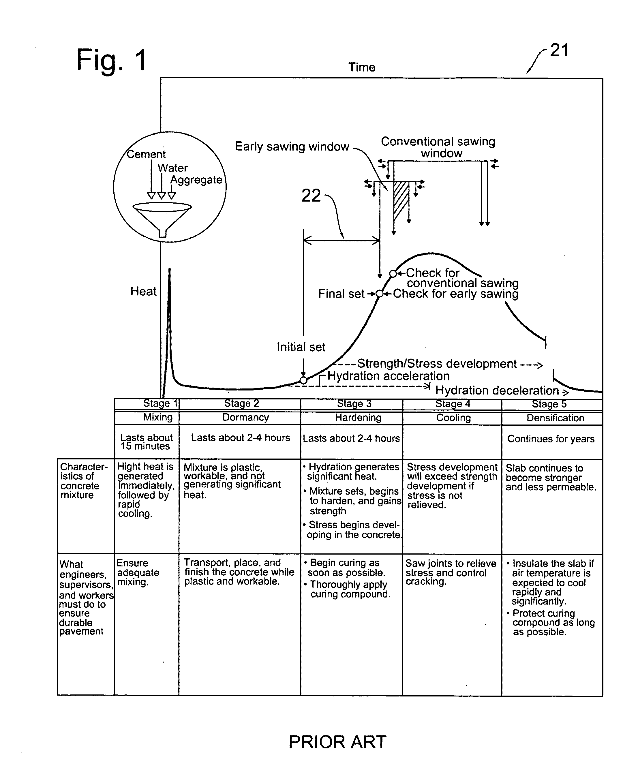
[0081]With primary attention directed now to FIG. 1, the concrete curing graph 21 plots heat against time through the five stages of hydration of freshly placed concrete. Time segment 22 indicates a time period in which troweling is preferably conducted, known as the “window of finishability.” As discussed earlier, troweling ideally begins with panning as known in the art when the concrete is plastic, towards the left portion of segment 22. Troweling graduates to blading as concrete hardens during the hardening stage, towards the right of segment 22. However, as concrete hardens, there is no clear demarcation point mandating the transition from pan troweling to blade troweling. Similarly, on a job site, the exact condition of curing concrete contacted by a given trowel during its travel is far from uniform. Therefore a panning trowel will sometimes encounter concrete that should be trowelled with a blade, and blading trowels often contact more plastic regions of concrete that ideall...


PUM


Abstract

High performance, multiple rotor, hydraulically driven riding trowels for finishing concrete have unloader valve circuitry for controlling hydraulic pressure. Each trowel has a rigid frame with two or more downwardly-projecting, bladed rotor assemblies that finish concrete. The rotor assemblies are tilted manually or hydraulically to effectuate steering and control. Blade pitch is controlled manually or hydraulically. The unloader valve system monitors drive pump pressure with a shuttle valve to derive an unloader pilot signal. A sequence valve responds to the unloader pilot signal to control a pressure valve that bypasses the normal foot control valve in an overpressure situation. The pressure control head signal normally applied to the hydraulic drive motor control heads is modified with a feedback signal to automatically control the associated pump swash plates. A gearbox may be disposed between the drive motors and rotors. Piston type and gear and vane type motors may power the rotors.

Description

CROSS-REFERENCE TO RELATED APPLICATIONS[0001]This utility patent application is based upon, and claims the filing date of, a prior pending utility application entitled “Hydraulic Riding Trowel with Automatic Load Sensing System,” Ser. No. 12 / 317,422, filed Dec. 22, 2008, which was in turn based upon a provisional application entitled “Hydraulic Riding Trowel with Motor Control. Hydraulic Feedback,” Ser. No. 61 / 009,182, was filed Dec. 27, 2007.BACKGROUND OF THE INVENTION[0002]I. Field of the Invention[0003]The present invention relates generally to hydraulically-driven, multiple rotor riding trowels with either hydraulic or manual steering, and with hydraulic control circuits used in such trowels. More particularly, the present invention relates to hydraulically-driven riding trowels using hydraulic circuitry including an unloader circuit responsive to hydraulic feedback for critically regulating the pump output flow to operate within the engine horsepower envelope. Riding trowels of...

Claims


Application Information

Patent Timeline
Patent Type & Authority Applications(United States)
IPC IPC(8): E01C19/42E01C19/22E01C19/12
CPCE04F21/24E04F21/247
Inventor ALLEN, J. DEWAYNEGUINN, TIMMY D.WALDON, EDWARD A.SUGG, SCOTT R.
Owner ALLEN ENG
Why Eureka
Try Eureka