Suspension arrangement

a suspension arrangement and vehicle technology, applied in the direction of resilient suspensions, vehicle springs, propulsive elements, etc., can solve the problems of limiting both on-road ground clearance, negligible camber change as the suspension operates, and not allowing sufficient movement of the suspension strut or hydraulic cylinder

Inactive Publication Date: 2005-09-20
GIBBS TECH
View PDF11 Cites 49 Cited by
  • Summary
  • Abstract
  • Description
  • Claims
  • Application Information

AI Technical Summary

Benefits of technology

[0008]According to a first aspect of the present invention, there is provided a suspension arrangement for an amphibious vehicle comprising a control arm pivotally mounted to the vehicle body and extending to a wheel support, the control arm and the wheel support being mounted for pivotal movement one relative to the other, and the wheel support including means for supporting a vehicle wheel, the suspension arrangement further comprising drive means pivotally mounted to the vehicle body in spaced relationship to the mounting for the control arm and operative to rotate the control arm a

Problems solved by technology

Conventional suspension arrangements do not allow for sufficient movement of a suspension strut or hydraulic cylinder without it interfering with the vehicle wheel being retracted.
The main drawback of this approach is that there is negligible camber change as the suspension operates, nor as the wheel is withdrawn.
However, such small wheels limit both on-road ground clearance, and the deadrise (the depth of the “vee” in lateral cross-section) on an amphibious veh

Method used


Image

  • Suspension arrangement
  • Suspension arrangement
  • Suspension arrangement

Examples


Embodiment Construction

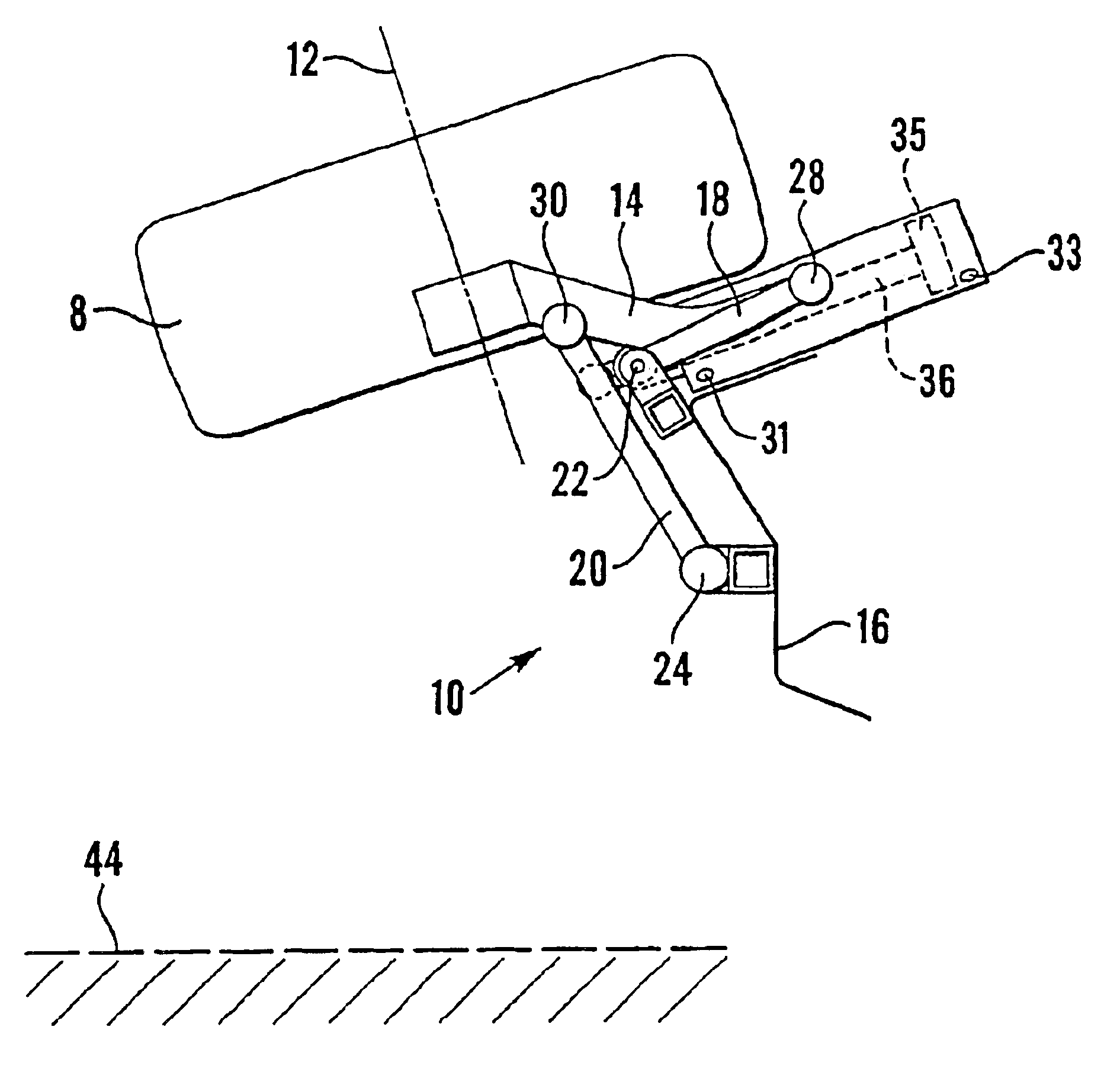
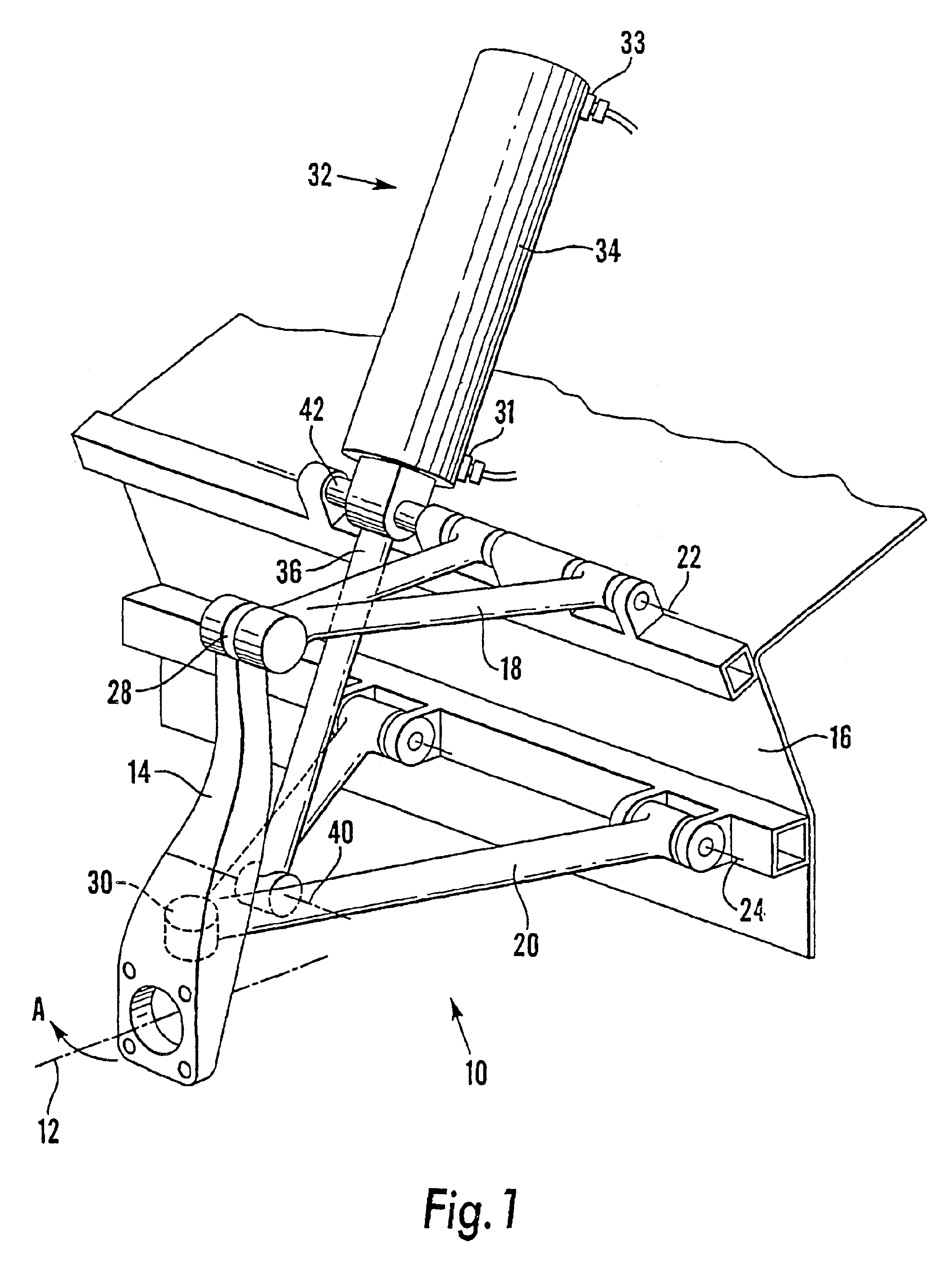
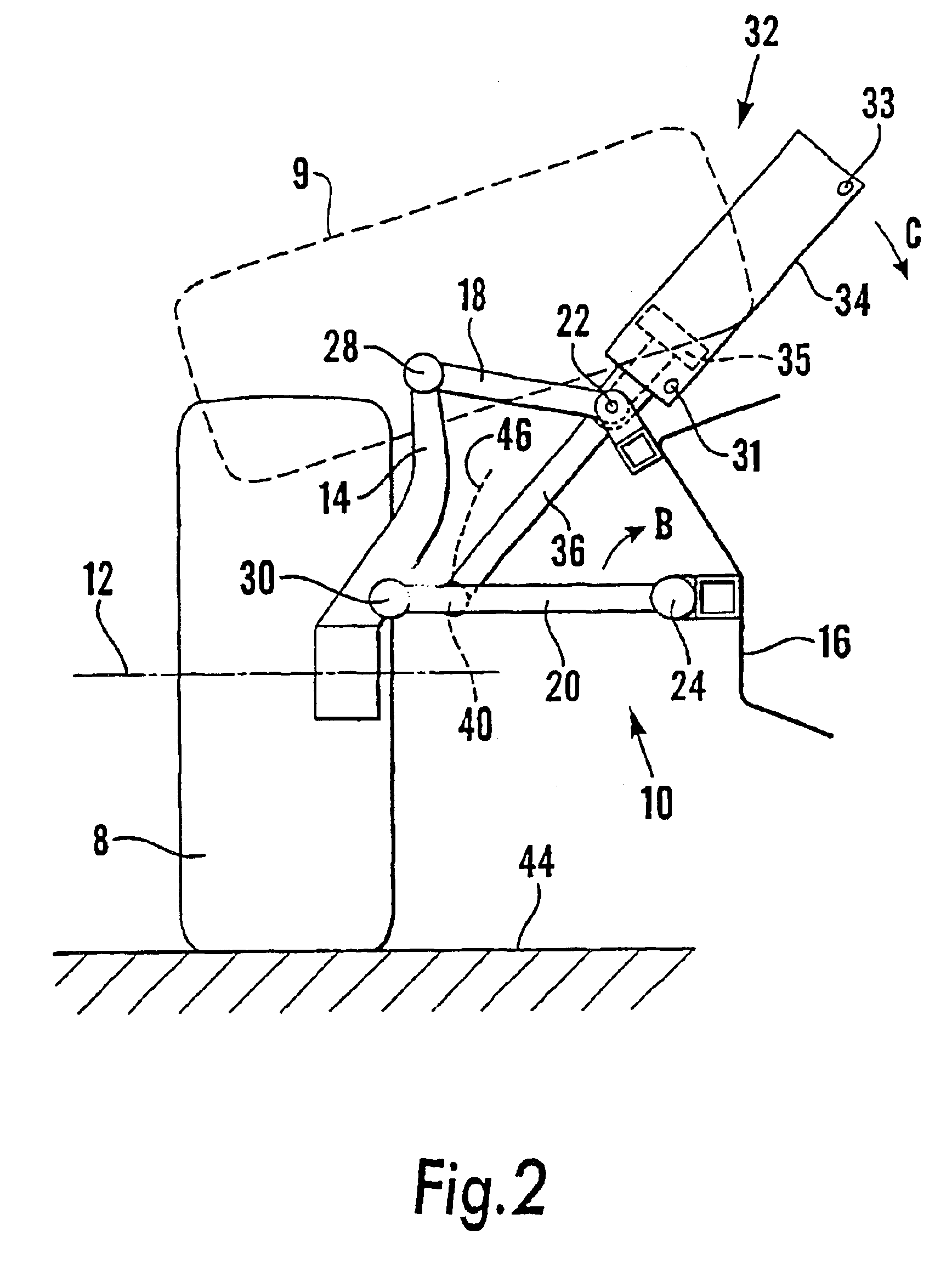
[0019]Referring firstly to FIGS. 1 and 2, a suspension arrangement for an amphibious vehicle wheel 8 is indicated generally at 10. The wheel 8 is mounted for rotation about an axis 12 on an axle (not shown), which is conventionally mounted to a wheel support upright 14. An upper control arm 18 and a lower control arm 20 support the wheel support upright 14 from the vehicle body 16. The control arms 18,20 are aligned with and spaced from each other and are pivotally mounted to the vehicle body 16 about respective parallel axes 22,24. This is commonly known as a double wishbone suspension arrangement.

[0020]Respective ball-joints 28,30 connect the control arms 18,20 to the wheel support upright 14. The ball joints allow turning movement of the wheel support upright 14, and-hence the wheel 8, in a lateral plane enabling steering in driving mode, as indicated by arrow A. The ball joints 28,30 also allow the control arms 18,20 to move together in parallelogram like manner during normal ro...


PUM


Abstract

Vehicle suspension having a control arm pivotally mounted to vehicle body. Wheel support is pivotally mounted to the control arm. A hydraulic strut is pivotally mounted to body at trunnion mount. The wheel may be protracted to be placed vertically on the road surface or retracted at an angle, for example to allow good marine performance in an amphibious vehicle. Strut may be extended or retracted by hydraulic fluid pumped through ports and may also be used for wheel springing and damping. As trunnion mount is part way up the strut, the strut can pivot out of the way of the retracing wheel. A second control arm may also be fitted; this may be part of a double wishbone wheel suspension.

Description

BACKGROUND OF THE INVENTION[0001]The present invention relates to a suspension arrangement for a vehicle, and more particularly, but not exclusively to a suspension arrangement for an amphibious vehicle.[0002]In conventional suspension arrangements a shock absorber or suspension strut is mounted at its upper end to a vehicle body, and at its lower end to a control arm of a vehicle wheel. The suspension strut usually consists of a cylinder and a shaft which telescopes within the cylinder, the cylinder and shaft being internally biased apart and damped. The cylinder is mounted on the control arm, and usually carries a seat for a coil spring. The coil spring is compressed between the seat and the vehicle body.[0003]In more sophisticated vehicle suspension arrangements, it is known to mount a hydraulic cylinder at its upper end to a vehicle body and at its lower end to a control arm of a vehicle wheel. The cylinder is usually connected to an accumulator in the form of a reservoir of hyd...

Claims


Application Information

Patent Timeline
IPC IPC(8): B60F3/00B60G3/18B60G3/20B62D61/12B62D61/00
CPCB60F3/003B60G3/20B62D61/12B60F2301/04B60G2200/144B60G2202/154B60G2202/413B60G2204/128B60G2204/129B60G2204/47B60G2300/28
Inventor ROYCROFT, TERENCE JAMES
Owner GIBBS TECH
Why Eureka
Try Eureka