Therapeutic limb covering using hydrostatic pressure

Inactive Publication Date: 2005-09-20
INCAPPE
View PDF103 Cites 138 Cited by
  • Summary
  • Abstract
  • Description
  • Claims
  • Application Information

AI Technical Summary

Benefits of technology

[0024]It is another object of the present invention to provide a therapeutic limb covering to

Problems solved by technology

First, the foam layer provides insulation from physical shock to the limb,

Method used


Image

  • Therapeutic limb covering using hydrostatic pressure
  • Therapeutic limb covering using hydrostatic pressure
  • Therapeutic limb covering using hydrostatic pressure

Examples


embodiment 10

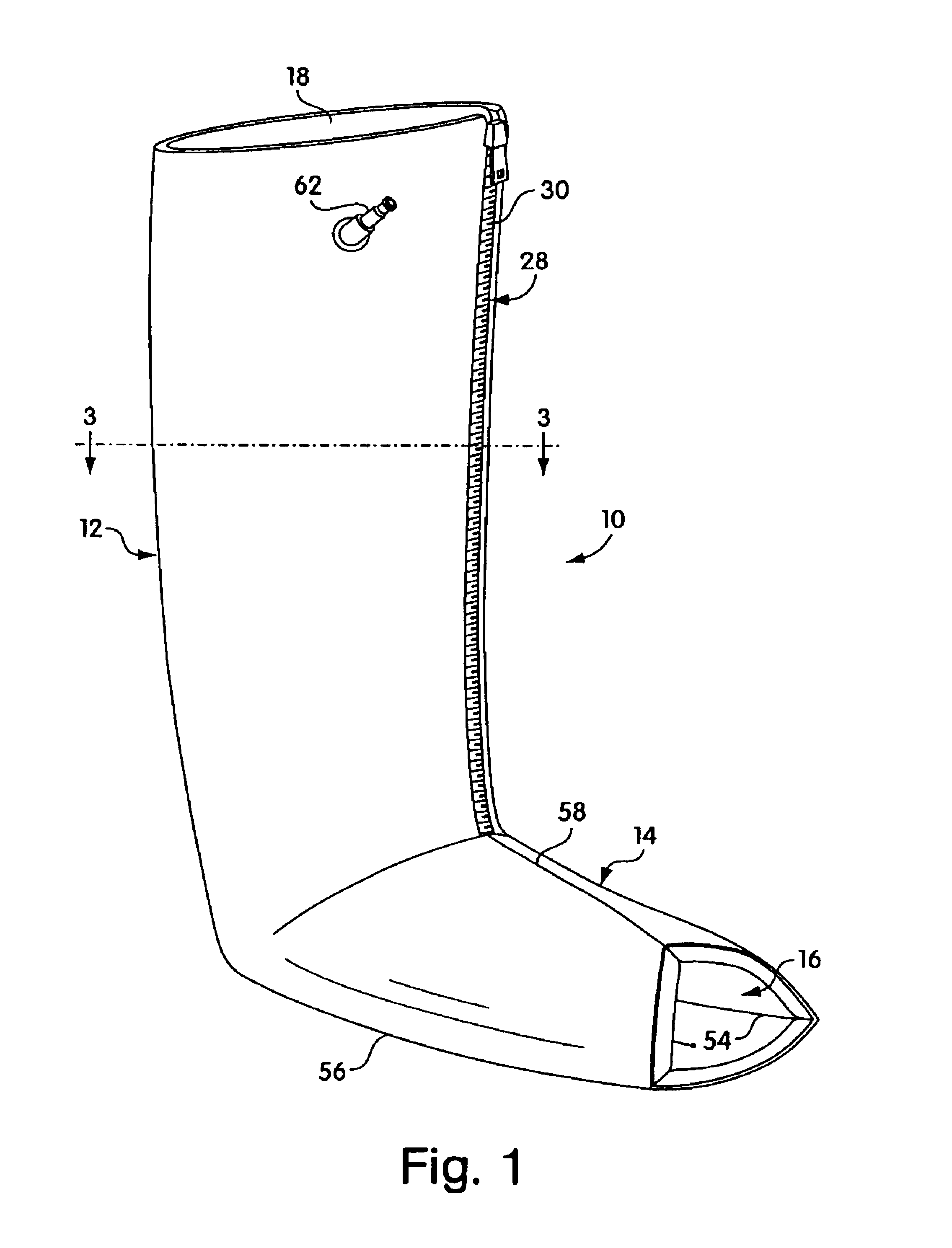
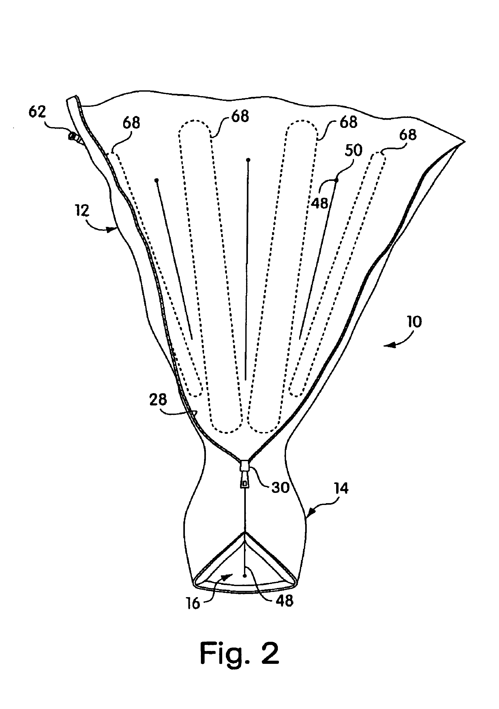
[0069]Another embodiment of the limb covering is shown in FIGS. 8 and 9. The boot covering 110 is similar to the boot embodiment 10 discussed in connection with FIGS. 1-7 above, but employs several alternate configurations that may be employed altogether as in the example discussed here or may be employed individually in a covering as desired by one practicing the invention. The covering 110 is similar in that it is formed from a substantially inelastic outer layer 122 and an elastic inner layer 124 bonded together at their peripheries to define a liquid tight bladder 126 between them. The resulting covering can be formed into a shape to cover the limb to be treated. In particular, the covering may be formed as a boot 110 for the foot and lower leg, or may be formed as a sleeve to be fitted over the arm as will be discussed below. In the case of the boot, a calf portion 112 and foot portion 114 are formed as well as corresponding calf and toe openings 118 and 116. The boot 110 also ...

first embodiment

[0075]FIG. 11 shows a detail of the arrangement of layers that form the covering 110 shown in FIGS. 8-10A. As shown in FIG. 11, the outer layer 122 may be considered as comprising all layers arranged external to the liquid held in the bladder 126. The inner layer 124 may be considered as comprising all layers positioned internal of the liquid held in the bladder: between the user's limb and the liquid. Thus, the outer layer 122, at its outermost surface, comprises a shell 132 that is flexible and may serve as a loop portion of a Velcro fastener. A suggested material for achieving this purpose is an engageable knit loop fabric as discussed above. On the inside surface 136 of the shell 132, a polyurethane coating 134 is applied as a backing material. Next, a structural support member 168, such as a polymer foam material may be adhered or bonded directly to the inside surface 136 of the shell 132, or may be captured against the shell 132 by a wall 138b of the bladder. The bladder 126 i...

embodiment 110

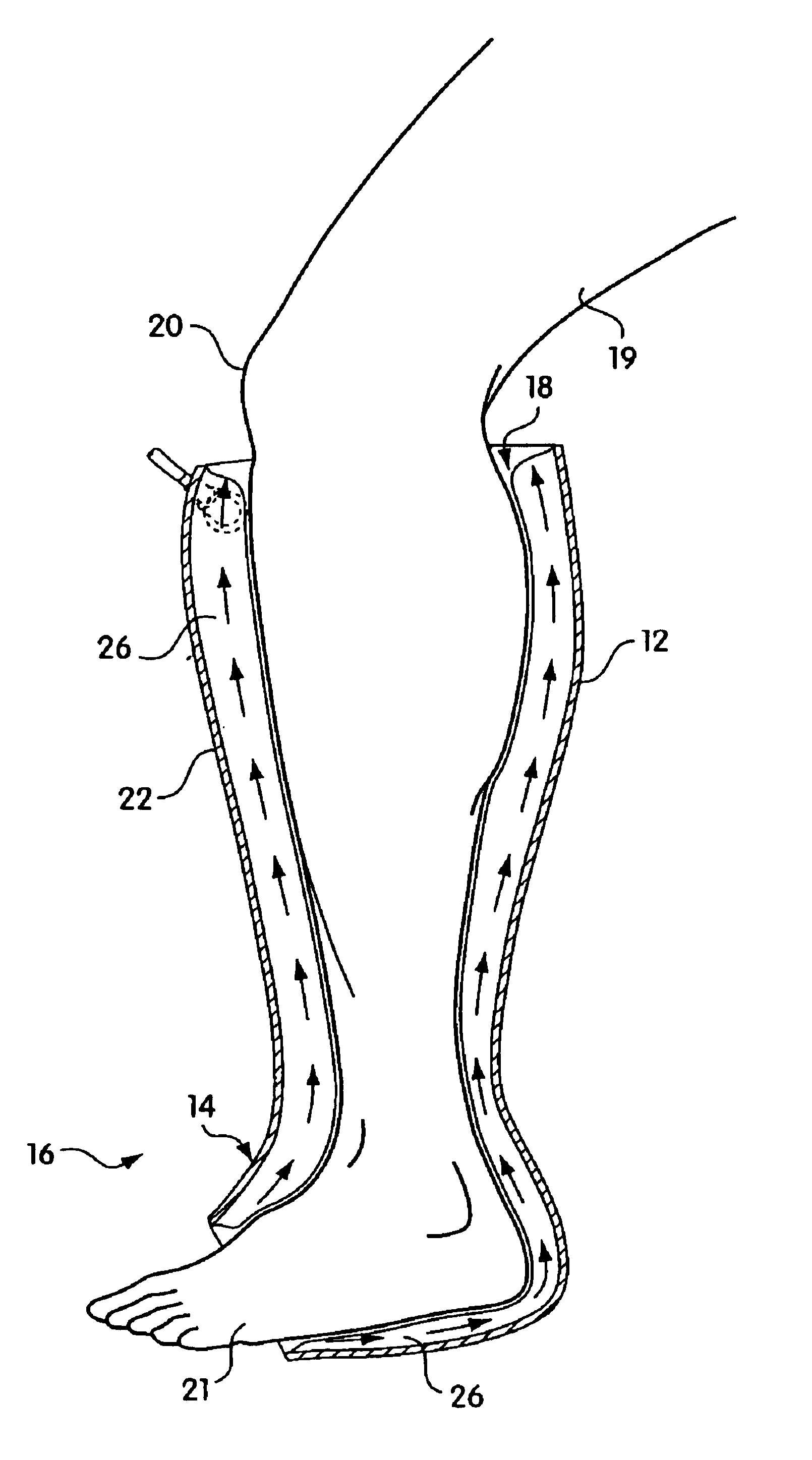
[0087]In use, the patient places the limb covering around the limb 19 prior to filling it with liquid. In the case of a boot limb covering releasable securement mechanism 30 is released to open the limb covering to permit donning over a bare foot or stocking and foot. It is noted that the following description of use refers to the boot 10 for simplicity, but that it should be understood that the boot embodiment 110 is used in the same manner. After the covering is slipped on so that the foot portion 14 covers the foot of the user, the securement mechanism 30 may be secured to tighten the calf portion 12 about the calf of the user. If provided, size adjusters 31 or Velcro fasteners may be tightened to customize the fit of the covering. A loose fitting shoe may then be slipped over the foot portion 14 of the covering. Liquid may then be added to the bladder 26 of the covering 10 through valve 62.

[0088]As shown in FIG. 20, liquid is added through valve 62 to the boot 10 that has been p...


PUM


Abstract

The present invention provides a therapeutic limb covering and an associated method of treating chronic swelling of a limb. The limb covering is uses hydrostatic pressure provided by liquid contained within the covering to apply pressure to the limb. The limb covering comprises a substantially non-distensible flexible outer layer, a distensible flexible inner layer joined together and a liquid tight bladder therebetween. The covering may be adapted for releasable securement about a limb such as an arm or a lower leg and foot of a patient. After placement on the limb, when the bladder is filled with a liquid, such as water, it expands to contact and apply pressure to the limb.

Description

FIELD OF THE INVENTION[0001]The present invention relates to devices and methods for the treatment of chronic swelling.BACKGROUND OF THE INVENTION[0002]Chronic swelling of a limb is a medical condition that results in pain, tissue breakdown and immobility for many patients. Such swelling is often caused by venous insufficiency or other disease such as lymphedema. In the case of venous insufficiency or venous stasis, the venous system of the extremities, particularly the lower extremities, experiences reduced blood flow. The reduced blood flow results from venous dysfunction in the extremity that limits the effective return of blood from the extremity back to the heart. The problem is exacerbated in lower extremities due to the effect of gravity, which must be overcome to move the blood back to the heart. However the arms are also susceptible to chronic swelling conditions such as may be caused by cancer of the lymph glands or post-mastectomy radiation treatment.[0003]A common treatm...

Claims


Application Information

Patent Timeline
IPC IPC(8): A61H23/04A61F5/01
CPCA61F5/0104A61F5/012A61H9/0078Y10S128/20Y10S2/911
Inventor KUIPER, HENDRIK KLAASREED, BOBBY E.ELLIS, DANNY EARL
Owner INCAPPE
Why Eureka
Try Eureka