Rod for a coating device, and process for producing the same

Inactive Publication Date: 2005-09-20
FUJIFILM CORP +1
View PDF4 Cites 3 Cited by
  • Summary
  • Abstract
  • Description
  • Claims
  • Application Information

AI Technical Summary

Benefits of technology

[0078]In this manner, the coating film is easily formed

Problems solved by technology

A first problem to be solved for a rod for a coating device in the prior art is that in the case that the rod 40 is used to perform high-speed coating (in particular, in the case that high-speed coating is applied to an anodizated aluminum web), convex portions 46 made in the rod 40 are abraded in a short time.
This is a serious problem for attainment of an improvement in productivity and energy-saving in the step of coating the web with the coating solution.
Even in a rod for a coating device in which no grooves are formed, its coating is partially abraded so that the same problem is caused.
However, no publications disclose which manner of ion plating should be used for the film formation.
However, the publications never consider that such examples are applied to a rod for a coating device.
A second problem to be solved for any coating device rod in the prior art is that in the case that a large shearing force or normal stress is applied to the surface of the rod when the rod is used, its coating is chipped or peeled from its base material.
A main cause for this is that residual stress generated in the coating is large.
The problem is generated not only in coating device rods in which grooves are made in the surface along the circumferential direction but also in coating device rods in which no grooves are made.
However, these publications never describe consideration of the two.
A third problem to be solved for any coating device rod in the prior art is that at the time of forming a coating thereon, very small cracks (chippings

Method used


Image

  • Rod for a coating device, and process for producing the same
  • Rod for a coating device, and process for producing the same
  • Rod for a coating device, and process for producing the same

Examples


first embodiment

[First Embodiment]

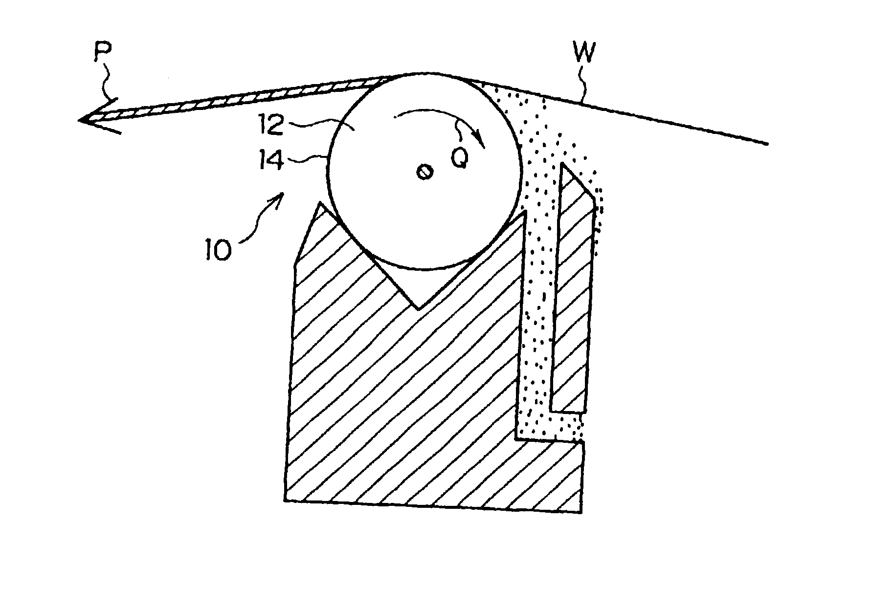
[0103]As illustrated in FIG. 1, a rod 10 according to the first embodiment is a rod for both of coating a running web W with a coating solution and adjusting the amount of the coating solution.

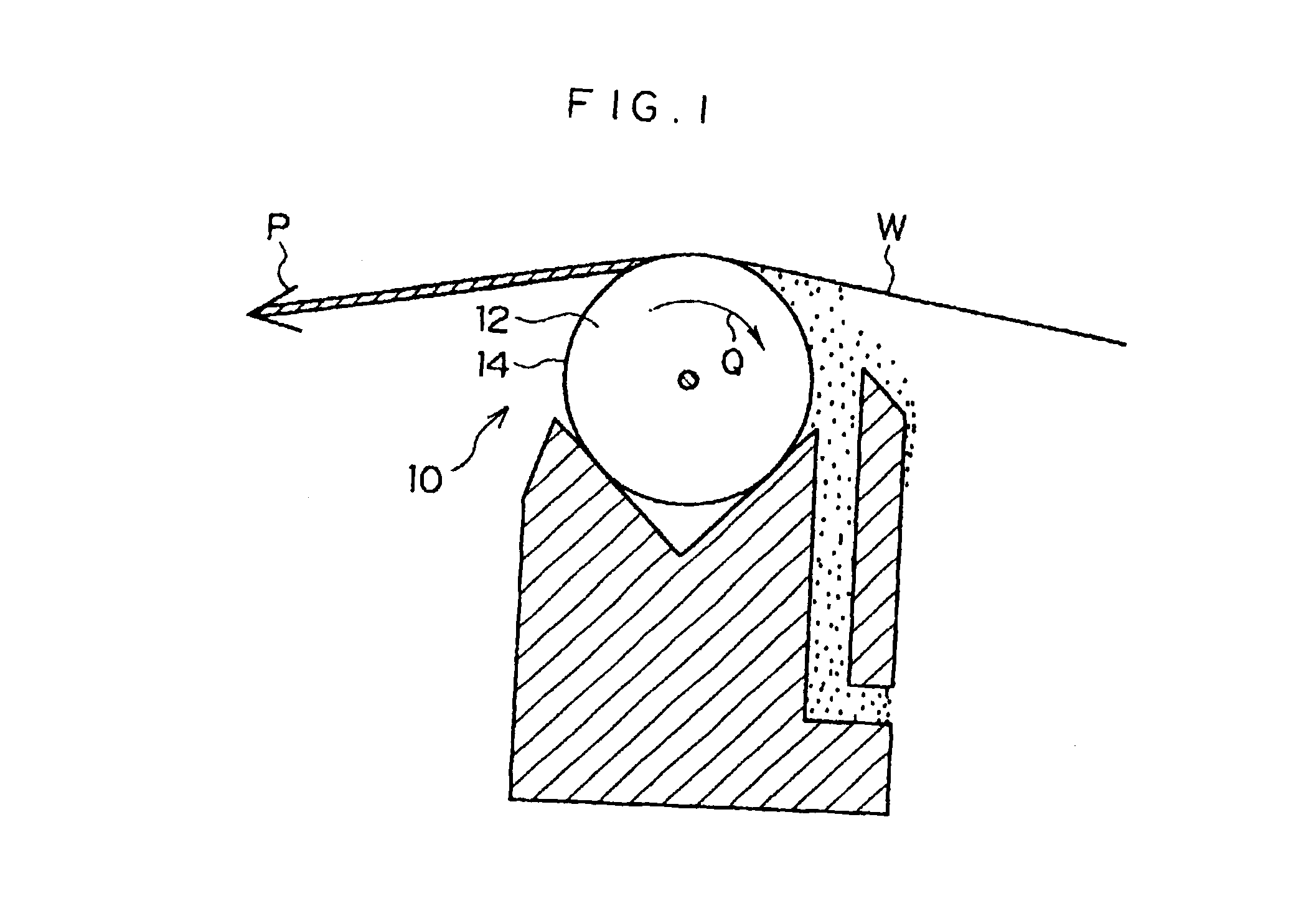
[0104]The rod 10 is a rod in which an abrasion-resistant coating 14 is formed on the circumferential surface of a columnar base material 12. In many cases, the base material 12 is made of stainless steel. In the circumferential surface of the base material 12, many grooves 18 are made along the circumferential direction (that is, a direction which is perpendicular to the axial direction and is along the running direction of the web W) (see FIG. 2) As a result, the circumferential surface of the rod is made irregular.

[0105]When the friction coefficient between the coating 14 and the web W is represented by μ, the material of the coating 14 is selected in such a manner that the value of the Vickers hardness Hv of the coating 14 satisfies the following formula (1):

Hv>1500×μ2+...

second embodiment

[Second Embodiment]

[0115]The following will describe a rod according to a second embodiment. In the second embodiment, to the same constituent elements as in the first embodiment are attached the same reference numbers. Description thereon is omitted.

[0116]A rod 220 (see FIG. 3) according to the second embodiment is a rod in which an abrasion-resistant coating 222 is formed on a base material 212 in an HCD manner (holocathode manner).

[0117]The surface state of the coating 222 formed in the HCD manner is superior in smoothness to that of any coating formed in any other manner of ion plating. For this reason, the contact area between the coating and the running web W increases so that a maximum shearing stress generated in the coating in the step of coating decreases. Since this makes the abrasion rate of the coating 222 small, the abrasion resistance of the coating 222 can be made better than in the first embodiment.

[0118]As the material of the coating 222, DLC (diamond-like carbon) ...

example 1

[0120]Base materials, made of stainless steel (SUS 304) and having a diameter of 13 mmφ, were used as the base materials 12 to produce rods in which materials of their coatings (coating species) were varied as a parameter. The coatings were formed by ion plating.

[0121]These rods were used as rods for performing both of the coating of the running web W and the adjusting of the amount of a coating solution. As illustrated in FIG. 1, experiments in which the web W running at a running speed of 50 m / minute was coated with the coating solution were made. The rotation direction Q of each of the rods was set such that the rod surface contacting the web W was shifted to the direction opposite to the web running direction P (see FIG. 1) Regarding physical properties of the coating solution, the viscosity thereof was 8 cp and the surface tension thereof was 22 mN / m. The formulation of the coating solution is shown in Table 1.

[0122]

TABLE 1Polyurethane resin of 4,4-diphenylmethane5.0 gdiisocyan...


PUM

PropertyMeasurementUnit
Temperatureaaaaaaaaaa
Thicknessaaaaaaaaaa

Abstract

A rod for a coating device, used when a continuously-running body is coated with a coating solution, includes: a columnar base material; and an abrasion-resistant coating formed on a circumferential surface of the base material. When a friction coefficient between the coating and the body is represented by μ, a Vickers hardness of the coating is represented by Hv, a thermal expansion coefficient of the base material is represented by α1×10⁻⁶/° C., a thermal expansion coefficient of the coating is represented by α2×10⁻⁶/° C., and a film thickness of the coating is represented by t μm, μ and Hv satisfy a predetermined relational expression, and/or α1, α2 and t satisfy another predetermined relational expression. Specifically, Hv>1500×μ2+1200 and/or |α1−α2|<3/(t−4)+7. The invention provides a process for producing a rod, for a coating device, on which an abrasion-resistant coating is formed on a base material to have a uniform thickness.

Description

BACKGROUND OF THE INVENTION[0001]1. Field of the Invention[0002]The present invention relates to a rod for a coating device, on the surface of which a coating having abrasion resistance is formed, and a process for producing the same, and more specifically relates to a rod for a coating device which is suitable for coating a body to be coated, such as a continuously-running web, with a coating solution, and a process for producing the same.[0003]2. Description of the Related Art[0004]It is widely performed that, when a photosensitive material, a photoengraving process material, a magnetic recording material, recording paper material, a photosensitive planographic printing plate, or the like is produced, a sheet-form or web-form body to be coated (substrate to be coated) made of a thin metal, paper, film or the like is continuously run in a longitudinal direction and simultaneously one single side thereof is coated with a coating solution (photosensitive solution).[0005]In many cases...

Claims


Application Information

Patent Timeline
IPC IPC(8): B05C11/02B05C1/08C23C14/02C23C14/06C23C14/22
CPCB05C1/0808B05C11/025C23C14/0641C23C14/22C23C14/025Y10T428/31
Inventor OSHIMA, ATSUSHI
Owner FUJIFILM CORP
Why Eureka
Try Eureka