Electronic equipment control system and control method

a control system and electronic equipment technology, applied in the direction of electric controllers, ignition automatic control, instruments, etc., can solve the problems of remote control signal not being received, operation complicated, and increasing operation functions,

Inactive Publication Date: 2005-09-20
PIONEER CORP
View PDF15 Cites 8 Cited by
  • Summary
  • Abstract
  • Description
  • Claims
  • Application Information

AI Technical Summary

Benefits of technology

[0022]In the case of being constructed thus, deterioration with time of the display part by supplying a power source to the second operation unit in a state hidden in the back of the first operation unit can be prevented effectively, and life extension and low power consumption of the whole apparatus can be achieved.
[0024]According to this aspect, when the remote control signal relates to use of a second operation unit function, the operation corresponding to the remote control signal is performed when the second operation unit is in the state capable of visual identification from the outside. On the other hand, the operation corresponding to the remote control signal is not performed when the second operation unit is not in the state capable of visual identification from the outside, so that an accidental action by a user can be prevented from being performed in the second operation unit due to an input miss in a state in which the second operation unit cannot be visually identified.

Problems solved by technology

In these car audio apparatus, operation functions tend to increase and the operation tends to become complicated.
Also, in the system capable of remote control while using the two operation units, when an operation key corresponding to a remote control signal is present in the side of the hidden operation unit, the remote control signal is not received or is made invalid.
As a result of these, the speedy remote control operation becomes difficult and it also has a bad influence on a psychological state of a driver.

Method used


Image

  • Electronic equipment control system and control method
  • Electronic equipment control system and control method
  • Electronic equipment control system and control method

Examples


Embodiment Construction

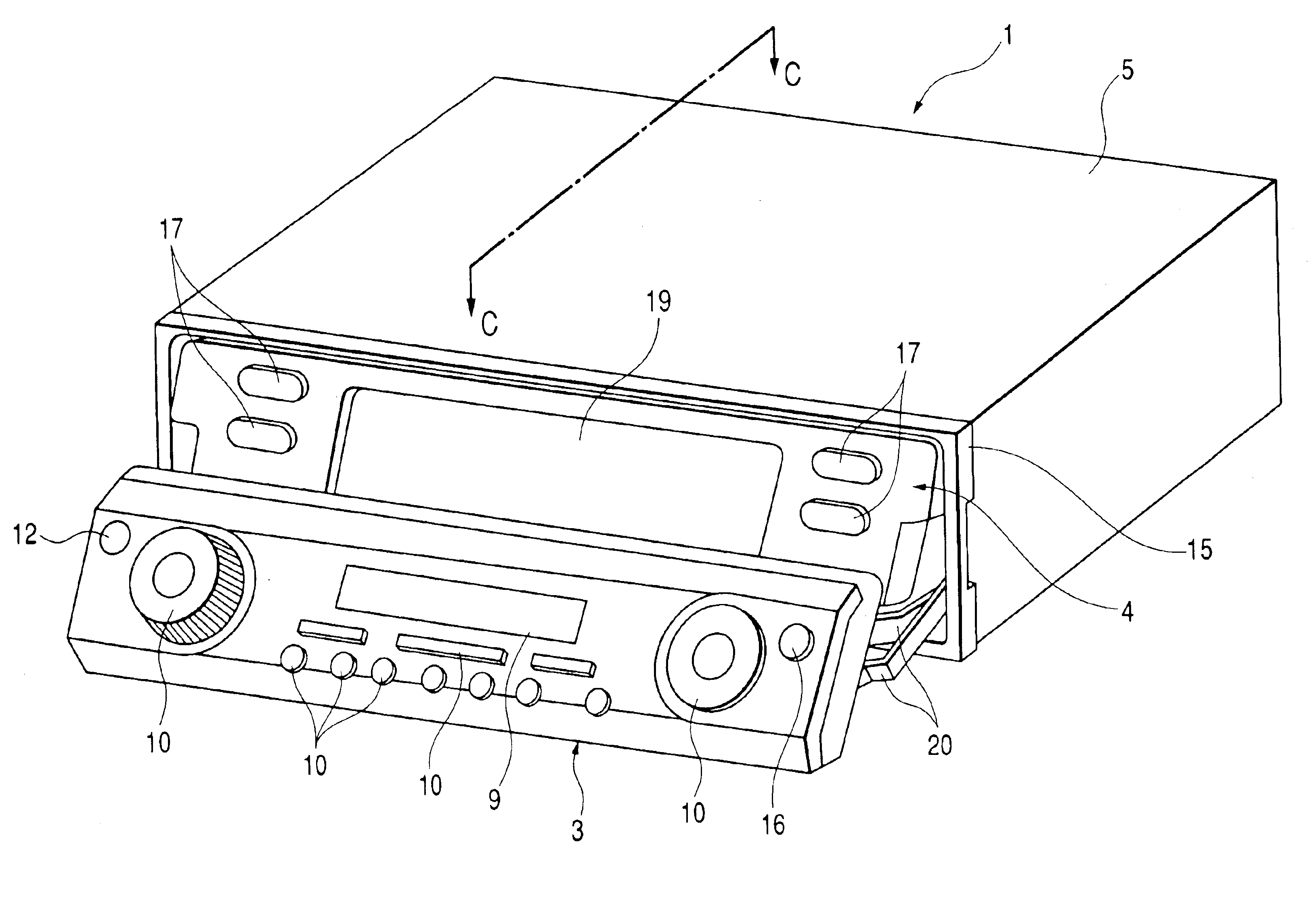
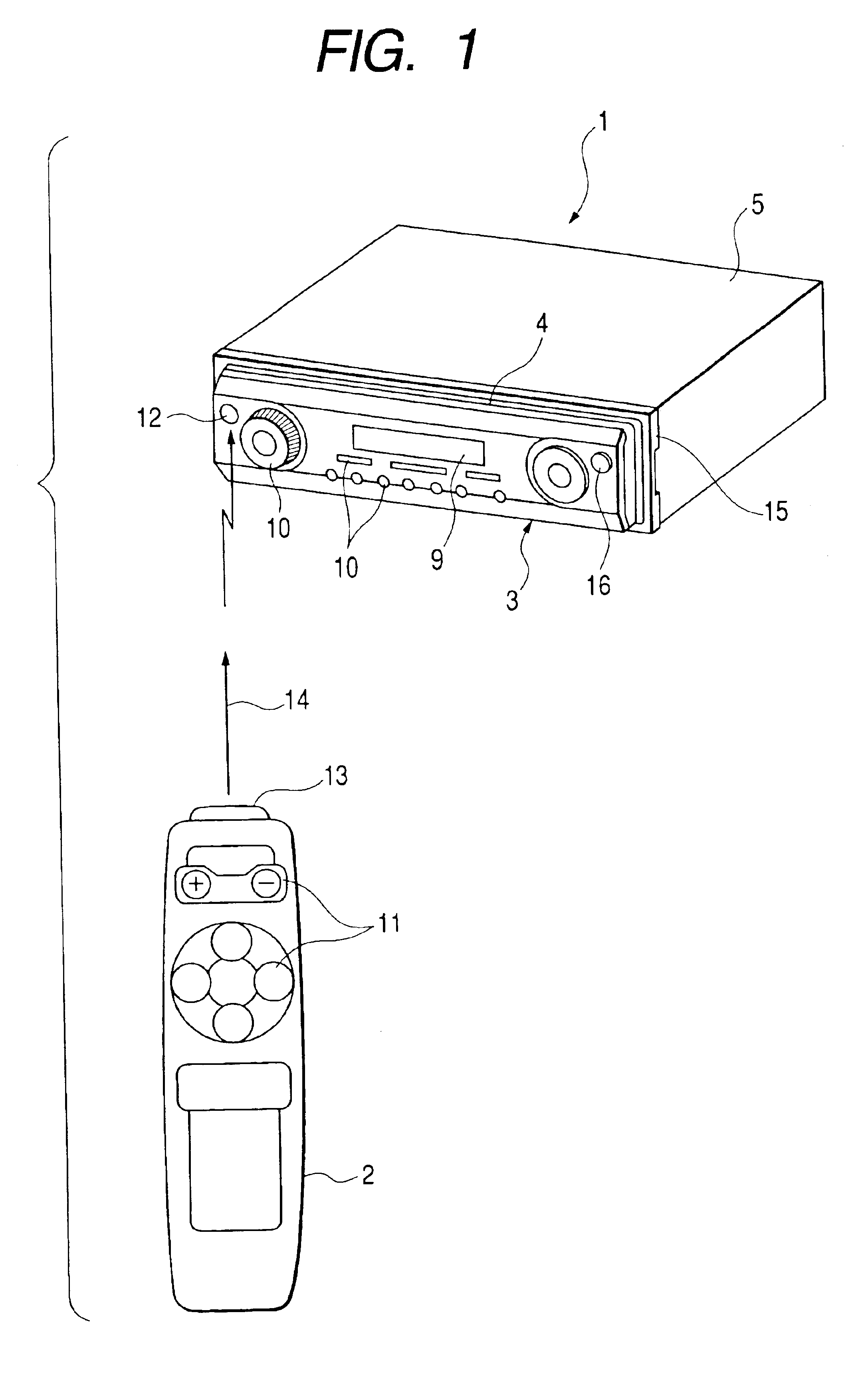
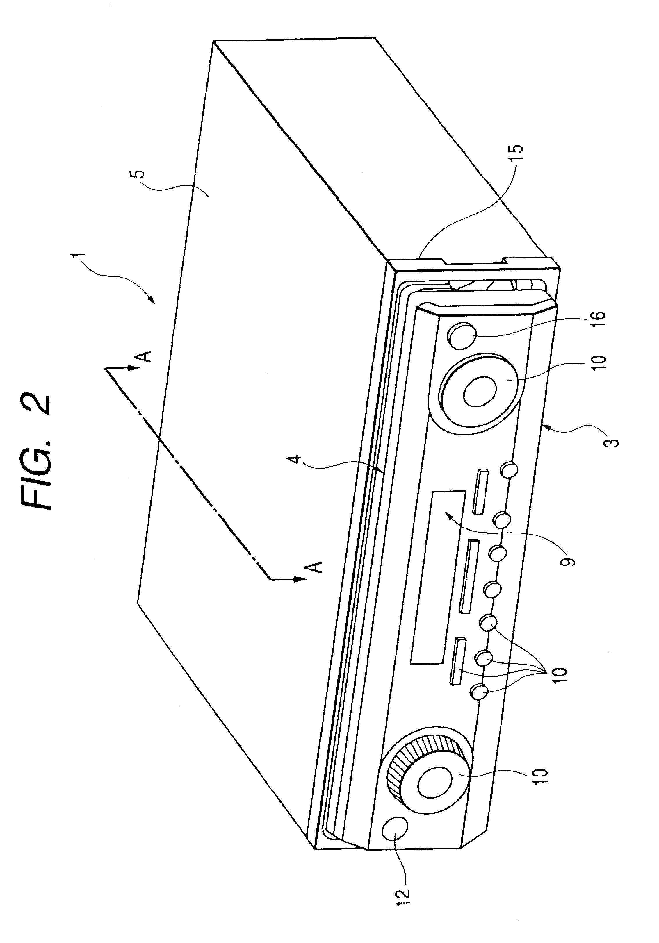
[0062]The present invention will be described below with reference to FIGS. 1 to 10. FIG. 1 is an external view showing an electronic equipment body and a remote control terminal forming an electronic equipment control system of the invention. FIG. 2 is a perspective view of the electronic equipment body in a first state and FIG. 3 is a partially sectional side view of its movable part. FIG. 4 is a perspective view of the electronic equipment body in a second state and FIG. 5 is a partially sectional side view of its movable part. FIG. 6 is a perspective view of the electronic equipment body in a third state and FIG. 7 is a partially sectional side view of its movable part. FIG. 8 is a block configuration diagram of the electronic equipment control system of the invention, FIG. 9 is a flowchart showing a flow of its operation and FIG. 10 is a sequence chart showing a relation of its component.

[0063]As shown in FIG. 1, the electronic equipment system of the invention is a system havi...


PUM


Abstract

An electronic equipment control system including an electronic equipment body and a remote control terminal for providing an operation instruction to the electronic equipment body. The electronic equipment body has a receiving part for receiving a remote control signal, a movable operation unit for operating the electronic equipment body, a fixed operation unit, and an arranging part for moving the movable operation unit to bring the fixed operation unit into a visually identifiable state. The remote control terminal has input keys for providing the operation instruction, and a sending part for sending operation information input by the input keys.

Description

[0001]The present disclosure relates to the subject matter contained in Japanese Patent Application No. 2001-373165 filed Dec. 6, 2001, which is incorporated herein by reference in its entirety.BACKGROUND OF THE INVENTION[0002]1. Field of the Invention[0003]The present invention relates to a control system and a control method of an electronic equipment mounted in a mobile unit such as a vehicle.[0004]2. Description of the Related Art[0005]Conventionally, various car audio apparatus such as a CD (Compact Disc) player, a DVD player, an MD (Mini Disc) player and an AM / FM tuner mounted in an instrument panel of a vehicle, and a car audio apparatus in which these are combined integrally or in which these are integrated with a navigation apparatus are used as electronic equipments. Also, there is a type having means for operating the electronic equipment by remote control.[0006]In these car audio apparatus, operation functions tend to increase and the operation tends to become complicate...

Claims


Application Information

Patent Timeline
Patent Type & Authority Patents(United States)
IPC IPC(8): H04B1/20H04Q9/00
CPCH04B1/202
Inventor MATUMOTO, ISAOKOBAYASHI, HIRONORINISHIDA, NORIFUMIFUKUYA, MAKOTOSHIBATA, NAOYANATORI, TETSUYAMAEDA, KOUJI
Owner PIONEER CORP
Why Eureka
Try Eureka