Display line drivers and method for signal propagation delay compensation

Inactive Publication Date: 2005-09-20
NAT SEMICON CORP
View PDF2 Cites 141 Cited by
  • Summary
  • Abstract
  • Description
  • Claims
  • Application Information

AI Technical Summary

Benefits of technology

[0010]It is an object of the present invention to compens

Problems solved by technology

Over time, however, display panels have become larger and pixel density has increased.
These changes in display panels have compounded the once minor delay problems to a point that they should no longer be considered negligible.
Furthermore, at points where display row and column signal lines cross, parasitic capacitance is observed between the conductive signal lines.
This parasitic capacitance may further slow signal propagation.
Practical factors currently limiting the state of the art dictate that such propagation delay be approximately 1 to 2.5 microseconds.
As discussed in greater detail hereinafter, display signal propagation delay may cause noticeable uneven display intensity or even disp

Method used


Image

  • Display line drivers and method for signal propagation delay compensation
  • Display line drivers and method for signal propagation delay compensation
  • Display line drivers and method for signal propagation delay compensation

Examples


Embodiment Construction

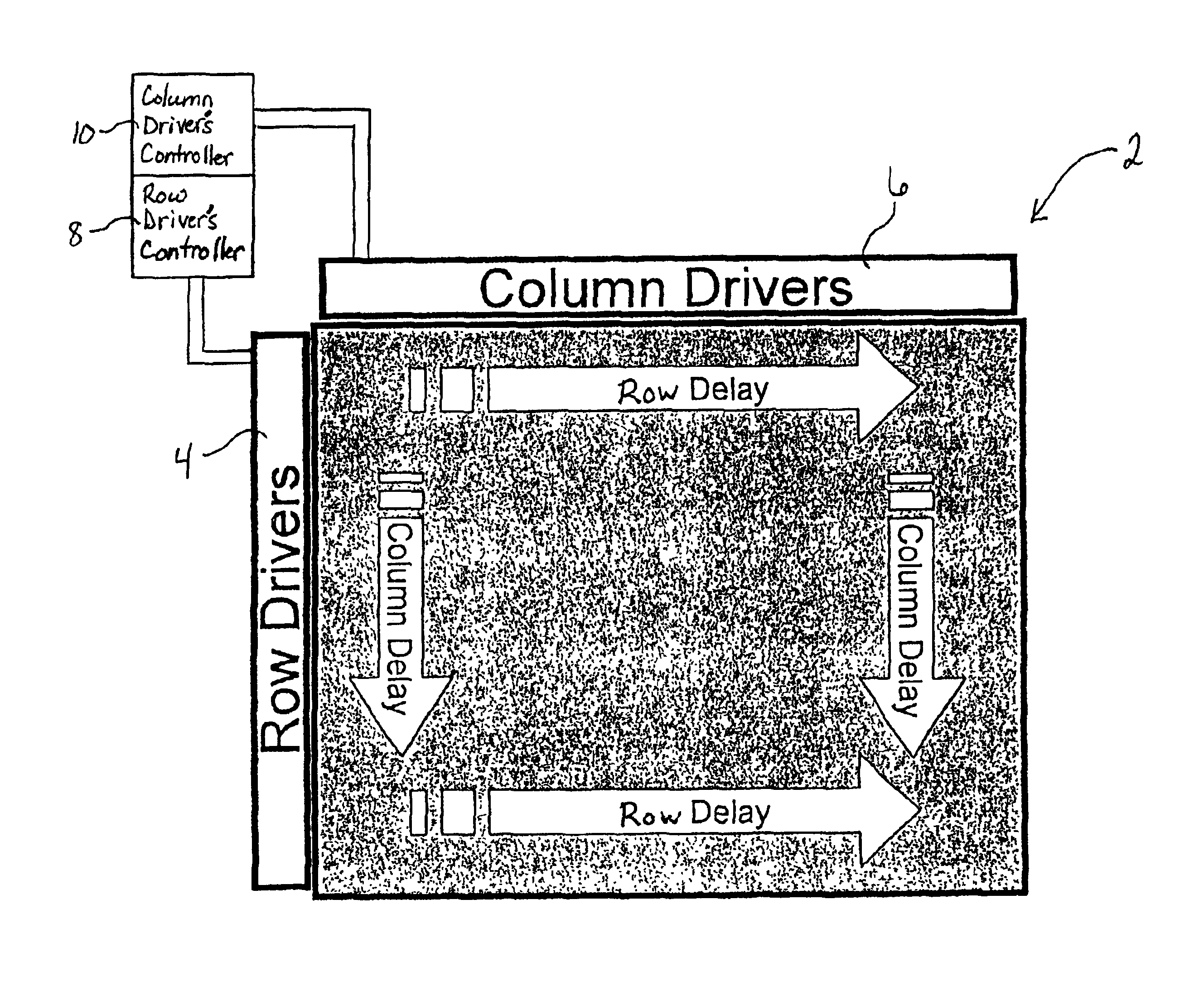
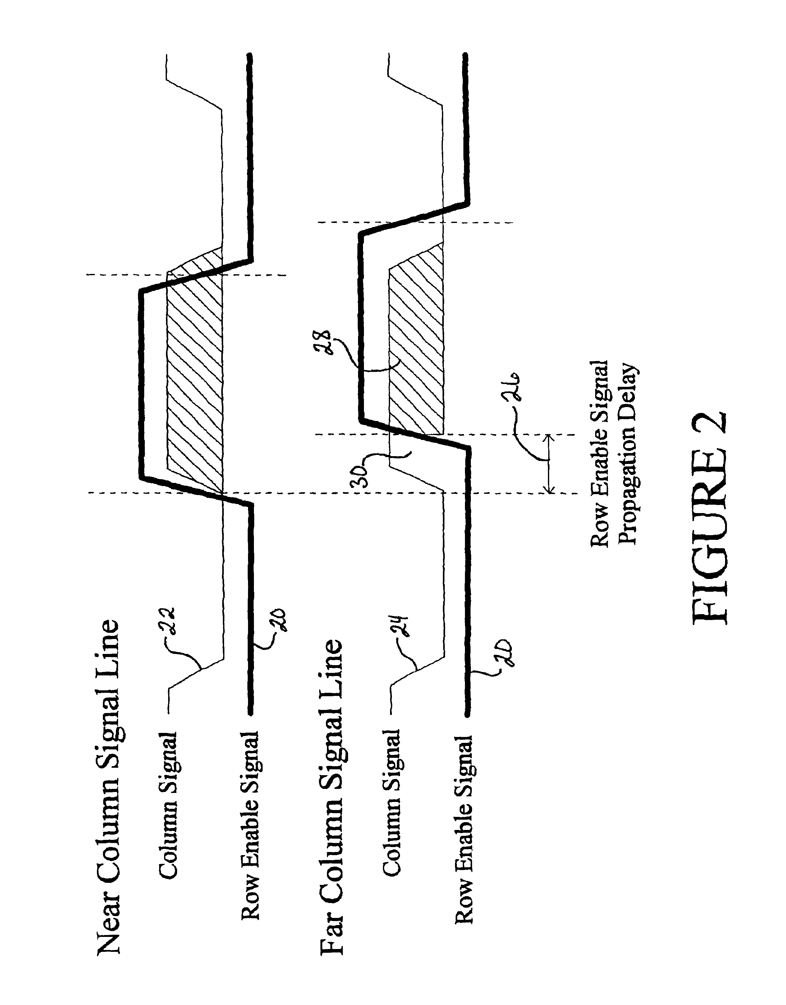
[0033]To illustrate the specific nature of the signal propagation delay problem, reference is made to FIG. 1. FIG. 1 illustrates a portion of a display panel 2 having a plurality of row drivers 4 along the left side of the display and a plurality of column drivers 6 along the top of the display. Rows associated with the row drivers 4 are ordered sequentially from top to bottom and are conventionally refreshed in sequential order. The row drivers 4 and column drivers 6 are respectively controlled by row driver and column driver controllers 8 and 10 respectively. The row and column drivers 4 and 6 may be formed in common circuitry with the respective row and column driver controllers 8 and 10, or as separate circuitry. Row and column drivers 4 and 6 may be respectively placed along the right and bottom sides of the display in addition to or instead of the left and top sides, respectively.

[0034]When it is time to refresh the first row of pixels, a row enable signal is produced from the...


PUM


Abstract

Methods and apparatus for compensating the effects of display signal propagation delay in a display panel are disclosed. The apparatus comprises circuitry in addition to conventional display driver circuitry for delaying display line timing signals by an amount approximating the delay found in corresponding display lines. By delaying display line timing signals, for example in a column driver, by an time approximately equal the delay experienced in a corresponding row enable signal line, capacitors associated with the display pixels charge more fully resulting in a more vivid display image. Methods for compensating the effects of display signal propagation delay involve generating a plurality of delayed display timing signals and activating display lines in response to those delayed timing signals.

Description

BACKGROUND OF THE INVENTION[0001]1. Field of the Invention[0002]The present invention relates generally to row and column drivers of a display panel. More particularly, the present invention relates to a method and apparatus for compensating propagation delay in display drivers through delaying a column driver enable signal by a time approximating the delay experienced by signals propagating in a corresponding row signal line. The present invention also relates to a method and apparatus for compensating propagation delay in display drivers through delaying a row driver enable signal by a time approximating the delay experienced by signals propagating in a corresponding column signal line.[0003]2. Description of the Relevant Art[0004]Many display panels, such as those used as televisions, computer monitors, and other video and stationary image displays, include a lattice of display signal lines formed in a plurality of rows and columns. Each junction of the lattice includes a switchi...

Claims


Application Information

Patent Timeline
IPC IPC(8): G09G3/36
CPCG09G3/3611G09G3/3674G09G3/3685G09G2320/0223
Inventor MCCARTNEY, RICHARD I.
Owner NAT SEMICON CORP
Why Eureka
Try Eureka