Alternative detector configuration and mode of operation of a time delay integration particle analyzer

a particle analyzer and detector configuration technology, applied in the field of three-dimensional structure, contents, and spectral composition analysis of objects, can solve the problems of low numerical aperture, slow existing system for 3d cell imaging, and large number of biological and medical procedures that are currently impractical

Inactive Publication Date: 2005-09-20
AMNIS CORP
View PDF45 Cites 58 Cited by
  • Summary
  • Abstract
  • Description
  • Claims
  • Application Information

AI Technical Summary

Benefits of technology

[0012]In TDI imaging of objects that was disclosed in previous pending applications, the image of the object moves synchronously with the pixilated signal (in the same direction and with the same speed), light forming each portion of the image is collected in the same portion of the pixilated signal over time, regardless of the motion. Conversely, if the image of the object moves asynchronously relative to the pixilated signal, (at a different speed and/or in a different direction), light forming each portion of the image at later times will not be collected in the same portion of the pixilated signal. By in

Problems solved by technology

There are a number of biological and medical procedures that are currently impractical due to limitations in cell and particle analysis technology.
This technique can be applied to a slide-mounted sample or a sample on a micro-fluidic chip, but generally with lower numerical apertures, due to the difficulty of coupling orthogonal collection systems to the flat sample

Method used


Image

  • Alternative detector configuration and mode of operation of a time delay integration particle analyzer
  • Alternative detector configuration and mode of operation of a time delay integration particle analyzer
  • Alternative detector configuration and mode of operation of a time delay integration particle analyzer

Examples


first preferred embodiment

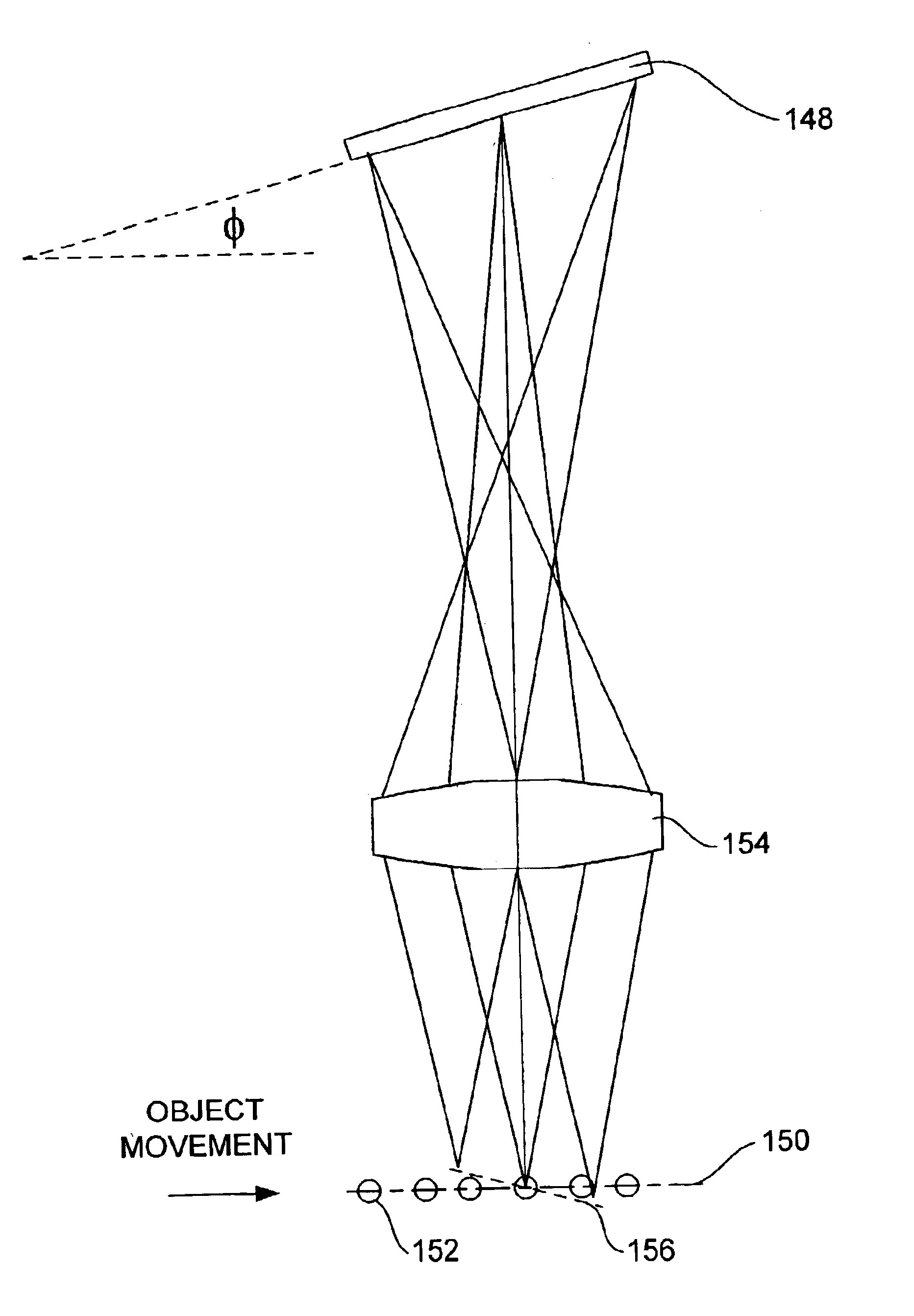
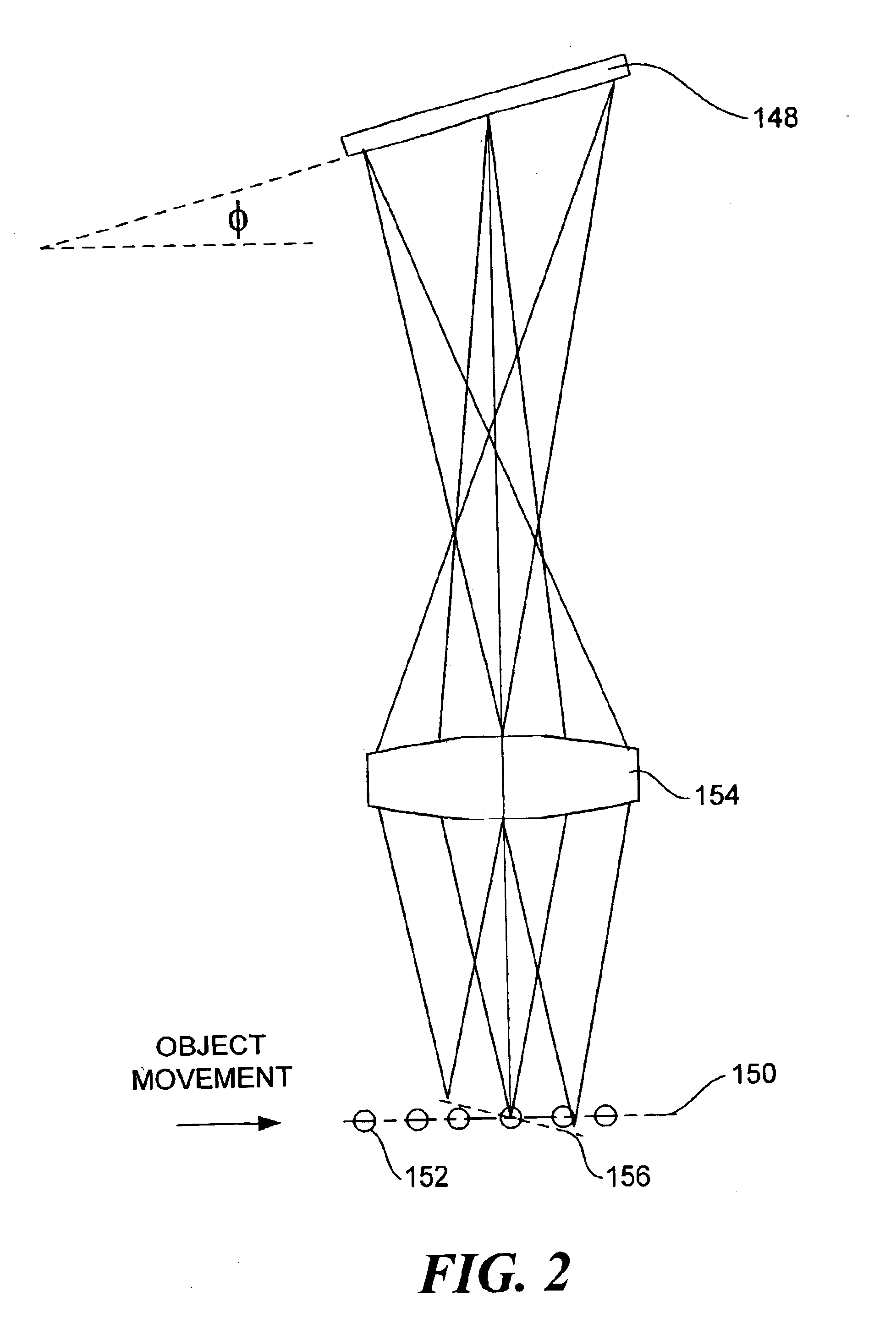
[0037]In accord with a first preferred embodiment, TDI clocking is synchronous with the motion of the image of the object, the signal is detected continuously, and the TDI detector is oriented in a plane inclined relative to the axis of motion of the object. Such a configuration is shown in FIG. 2 and it includes a TDI detector 148 that is tilted at an incline angle φ relative to an object motion axis 150. An object 152 is traveling along object motion axis 150 and is imaged on TDI detector 148 by an imaging lens 154. The inclination of the detector plane produces an inclined plane of focus 156, as illustrated in the Figure. In this configuration, measurements taken at different times will have different planes of focus within the object. However, because the first preferred embodiment employs synchronous clocking and continuous detection, only a single image is formed. Synchronous clocking with an inclined detector requires a different clocking frequency than when the detector is p...

second preferred embodiment

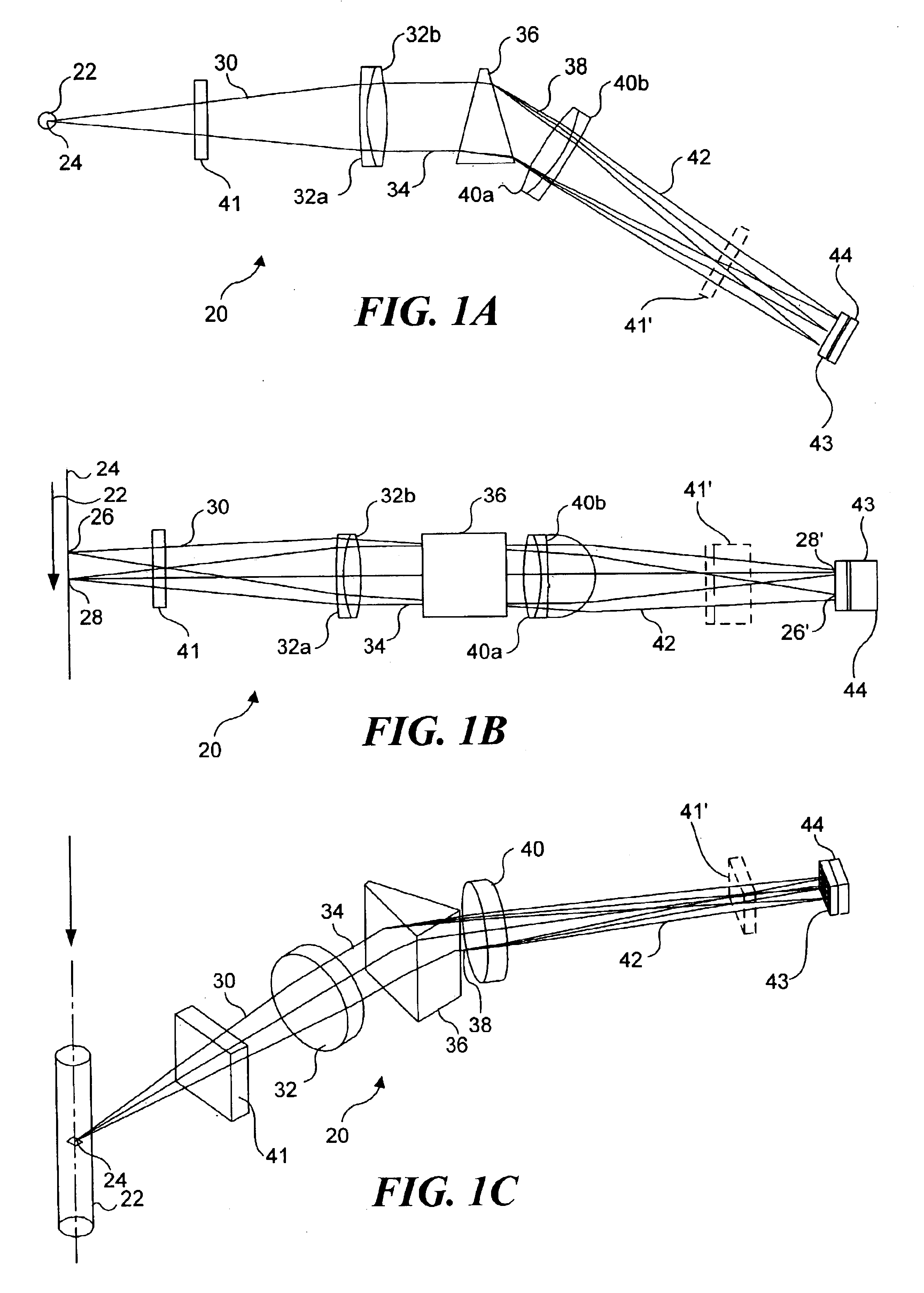
[0042]Like the first preferred embodiment, the second preferred embodiment employs a TDI detector inclined at an angle φ relative to the apparent axis of motion of the object. However, unlike the first embodiment, in the second preferred embodiment, signal detection is discontinuous. Discontinuous detection can occur as a result of employing a pulsed laser or other type of pulsed or strobed light source to illuminate the object. If the object being imaged is chemiluminescent or if the light from the object is continuous for some other reason, such as the object being illuminated by a continuous light source, a shutter or gated image intensifier can be employed between the object and the detector to produce discontinuous detection, such as described above with reference to shutter 41 and gated image intensifier 43 in FIGS. 1A-1C.

[0043]Also, unlike in the first preferred embodiment, a signal readout from the TDI detector in the second preferred embodiment is asynchronous, such that th...


PUM


Abstract

Light from an object moving through an imaging system is collected, dispersed, and imaged onto a time delay integration (TDI) detector that is inclined relative to an axis of motion of the object, producing a pixilated output signal. In one embodiment, the movement of the image object over the TDI detector is asynchronous with the movement of the output signal producing an output signal that is a composite of the image of the object at varying focal point along the focal plane. In another embodiment, light from the object is periodically incident on the inclined TDI detector, producing a plurality of spaced apart images and corresponding output signals that propagate across the TDI detector. The inclined plane enables images of FISH probes or other components within an object to be produced at different focal points, so that the 3D spatial relationship between the FISH probes or components can be resolved.

Description

RELATED APPLICATIONS[0001]This application is a continuation of a patent application Ser. No. 09 / 932,844, filed on Aug. 17, 2001, now U.S. Pat. No. 6,583,865, which is based on a prior co-pending provisional application Ser. No. 60 / 228,078, filed on Aug. 25, 2000, the benefits of the filing dates of which are hereby claimed under 35 U.S.C. § 119(e) and 35 U.S.C. § 120.FIELD OF THE INVENTION[0002]This invention generally relates to imaging objects or particles for purposes of detection and analysis, and more specifically, to a system and method for analyzing the three dimensional structure, contents, and spectral composition of objects, such as cells, which may be in motion.BACKGROUND OF THE INVENTION[0003]There are a number of biological and medical procedures that are currently impractical due to limitations in cell and particle analysis technology. Examples of such procedures include battlefield detection and monitoring of both known and unknown toxins, non-invasive prenatal genet...

Claims


Application Information

Patent Timeline
IPC IPC(8): G01N15/14G01N21/64G01N15/00G01N15/02G01N21/27G06K9/00
CPCG01J3/02G01J3/0208G01J3/0232G01J3/14G01J3/2823G01J3/2889G01N15/14G01N21/6458G06K9/00127G01N2015/1497G06V20/69
Inventor BASIJI, DAVID A.ORTYN, WILLIAM E.
Owner AMNIS CORP
Why Eureka
Try Eureka