
Optical lens apparatus and associated method

a technology of optical lenses and apparatuses, applied in the field of optical devices, can solve the problems of passive optical lenses being exposed to slight condition changes, affecting the operation of the optical lens, and affecting the operation of the optical lens

Active Publication Date: 2005-09-20
CISCO TECH INC
View PDF77 Cites 21 Cited by
  • Summary
  • Abstract
  • Description
  • Claims
  • Application Information

AI Technical Summary

Problems solved by technology

Optical lenses, as with most optical devices, are susceptible to changes in such operating parameters as temperature, device age, device characteristics, contact, pressure, vibration, humidity, etc.
Providing such packaging is extremely expensive.
Even if such packaging is provided, passive optical lenses may be exposed to slight condition changes.
If the characteristics of a passive optical lens is altered outside of very close tolerances, then the optical lens will not adequately perform its function.
In other words, there is no adjustability to the passive optical lenses.

Method used


Image

  • Optical lens apparatus and associated method
  • Optical lens apparatus and associated method
  • Optical lens apparatus and associated method

Examples


Embodiment Construction

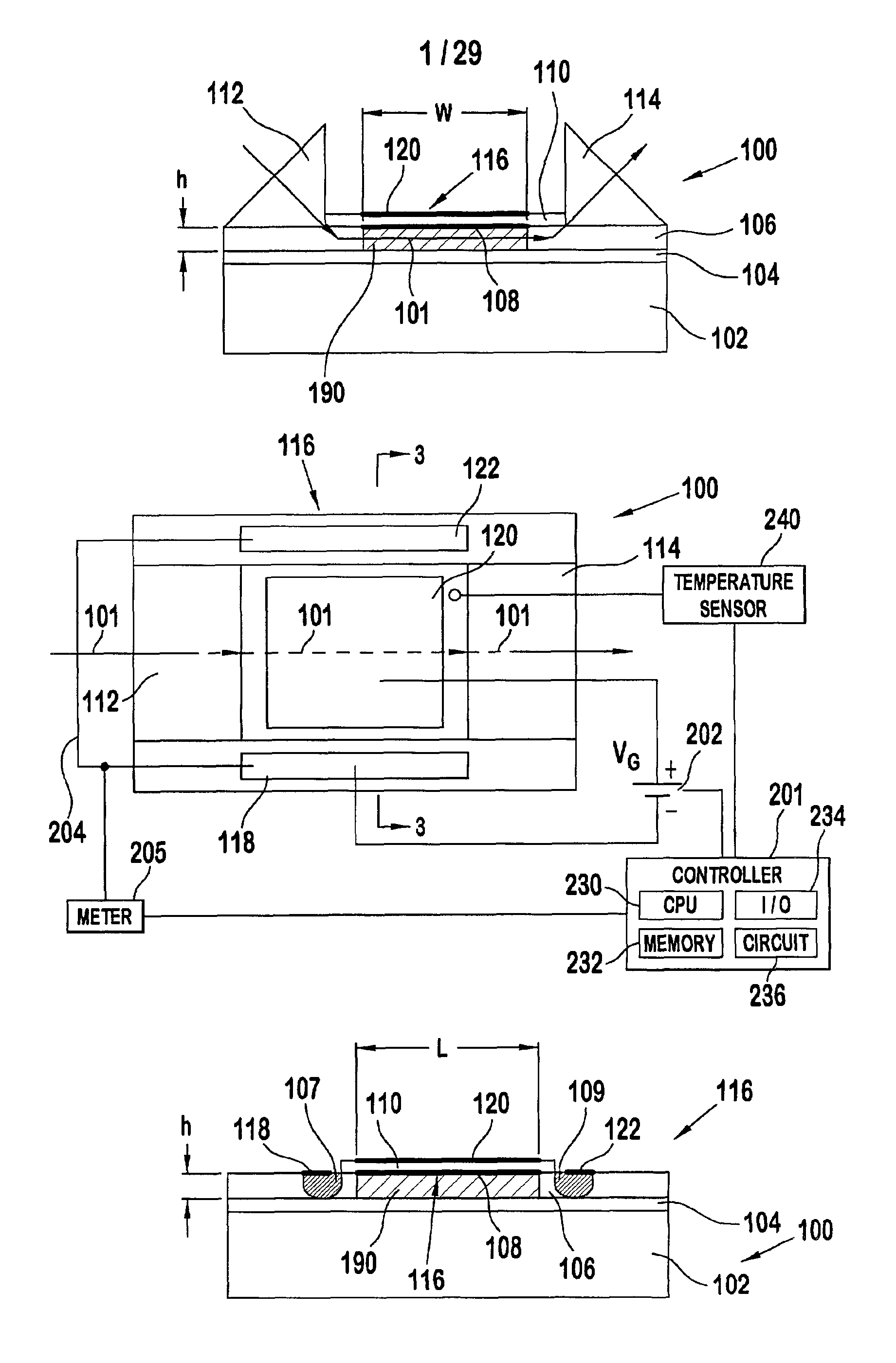
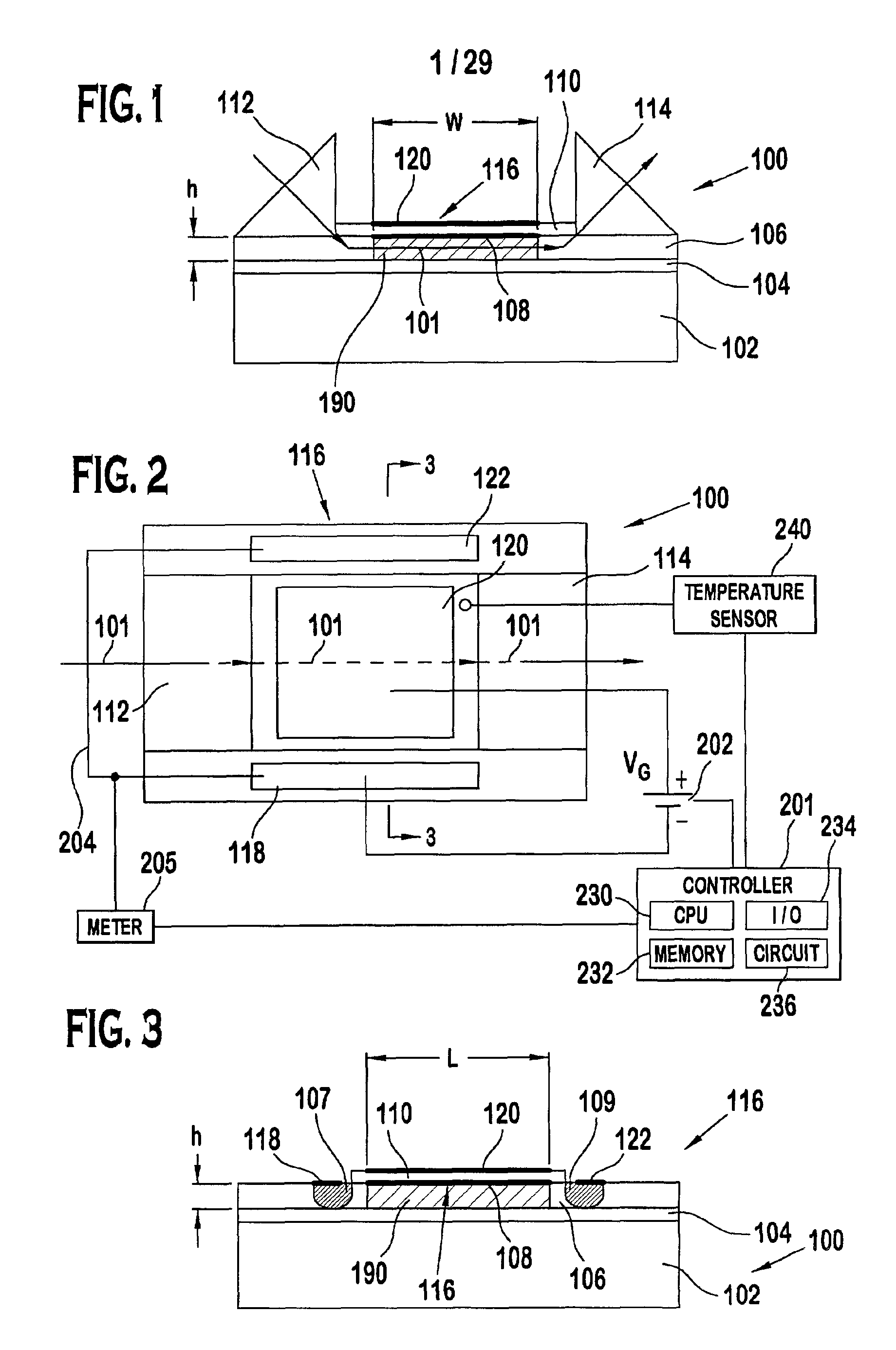
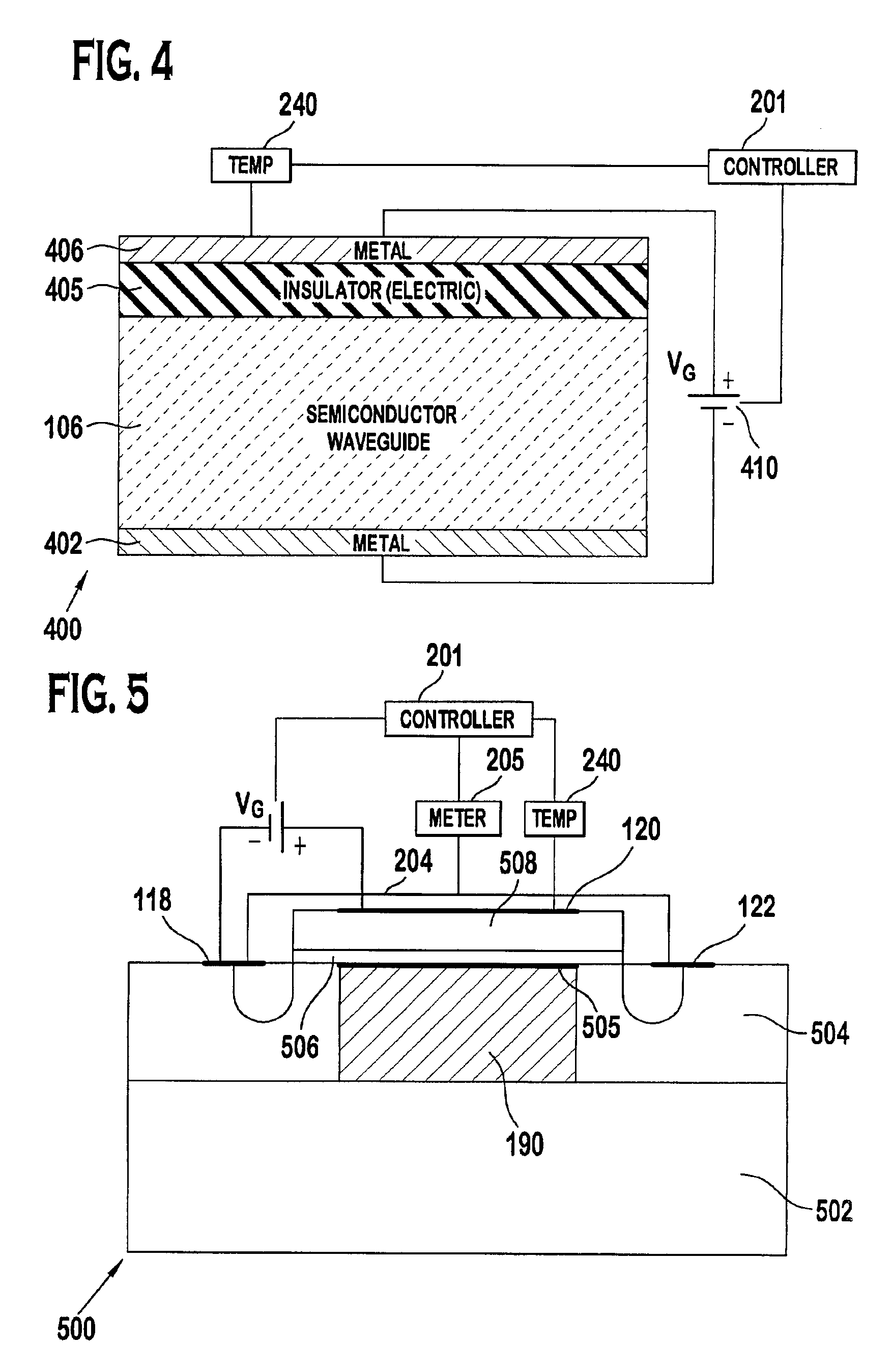
[0060]The present disclosure provides multiple embodiments of optical waveguide devices in which light travels within a waveguide. Different embodiments of optical waveguide devices are described that perform different functions to the light contained in the waveguide. Altering the shape or structure of an electrode(s) can modify the function of the optical waveguide device 100.

[0061]There are a variety of optical waveguide devices 100 that are described in this disclosure. Embodiments of optical waveguide devices include a waveguide located in a Field Effect Transistor (FET) structure as shown in FIGS. 1 to 3; a waveguide associated with metal oxide semiconductor capacitor (MOSCAP) structure is shown in FIG. 4; and a waveguide located in the High Electron Mobility Transistor (HEMT) as shown in FIG. 5. In MOSCAPs, one or more body contact(s) is / are separated from the gate electrode by a semiconductor waveguide and an electrical insulator. In the embodiment of FETs applied to the pre...


PUM


Abstract

An apparatus and associated method for controlling the propagation constant of a region of focusing propagation constant in an optical waveguide. The method comprising positioning an electrode of a prescribed electrode shape proximate the waveguide. A region of focusing propagation constant is projected into the waveguides that corresponds, in shape, to the prescribed electrode shape by applying a voltage to the shaped electrode. The propagation constant of the region of focusing propagation constant is controlled by varying the voltage. Light of certain wavelengths passing through the region of focusing propagation constant has a variable focal length.

Description

FIELD OF THE INVENTION[0001]This invention relates to optical devices, and more particularly to optical waveguide devices.BACKGROUND OF THE INVENTION[0002]In the integrated circuit industry, there is a continuing effort to increase device speed and increase device densities. Optical systems are a technology that promise to increase the speed and current density of the circuits. Optical lenses are optical devices that are configured to focus light. It is known to focus light using optical devices. For instance, light flowing through Bragg gratings are known to focus on a focal point. Optical lenses can be discrete elements made from glass or clear plastic or alternatively can be formed from a semiconductor material, such as silicon.[0003]Optical lenses, as with most optical devices, are susceptible to changes in such operating parameters as temperature, device age, device characteristics, contact, pressure, vibration, humidity, etc. As such, the optical lenses are typically contained...

Claims


Application Information

Patent Timeline
IPC IPC(8): G02F1/01G02F1/025G02B5/04G02B27/28G02B6/124G02B6/12G02B6/28G02F1/295G02B6/10G02B6/34G02F1/29G02B6/122H01L27/12G02F1/015G02B6/42G02B6/43
CPCB82Y20/00G02B5/045G02B6/10G02B6/12004G02B6/12007G02B6/12011G02B6/12016G02B6/12033G02B6/1225G02B6/1228G02B6/124G02B6/272G02B6/2861G02B6/29325G02B6/29395G02B27/285G02F1/025G02F1/295H01L27/1203G02B6/12026G02B6/12028G02B6/29349G02B6/29358G02B6/29391G02B6/34G02B6/4232G02B6/43G02B2006/12038G02B2006/12061G02B2006/12097G02B2006/12104G02B2006/12107G02B2006/12114G02B2006/12135G02B2006/12161G02B2006/12164G02B2006/12176G02F1/0147G02F2001/0152G02F2201/20G02F1/0152
Inventor DELIWALA, SHRENIK
Owner CISCO TECH INC
Learn More