Methods for optimizing magnetic resonance imaging systems

a magnetic resonance imaging and optimization technology, applied in the field of optimizing magnetic resonance imaging systems, can solve problems such as undesirable requirements, and achieve the effects of minimizing the volume of the coil, reducing the power consumption of the resistive coil, and accurate and efficient determination of the arrangemen

Inactive Publication Date: 2005-09-20
NEW YORK UNIV
View PDF3 Cites 6 Cited by
  • Summary
  • Abstract
  • Description
  • Claims
  • Application Information

AI Technical Summary

Benefits of technology

[0005]Another object of the invention is a computer-implemented method for designing electromagnetic coil arrangements that generate uniform magnetic fields, which method will accurately and efficiently determine an arrangement that minimizes the volume of the coils.
[0006]Yet another object of the invention is a computer-implemented method for designing electromagnetic coil arrangements that generate uniform magnetic fields, which method will minimize the power consumption of resistive coils.
[0008]In accordance with one aspect of the present invention, a practical numerical method is described of precisely determining, in many cases, minimum volume coil arrangements. An important advantage of the method is that the solutions it generates are guaranteed to be global, rather than merely local, minimums.
[0012]The method of the invention is useful for designing both superconducting and resistive electromagnets. While minimizing the coil volume is often of central importance for large superconducting magnets, for large resistive magnets, minimization of the power consumption is typically a primary design goal. For a given current density, the minimum power and minimum volume coil arrangements are the same. By computing the minimum volume solution for a range of current densities, the arrangement needing the absolute minimum amount of power can be found.

Problems solved by technology

Many difficulties are encountered in such a magnet design problem, and many solutions have been proposed.
While the methods disclosed by Kitamura and Xu have benefits, they also have requirements that are undesirable.

Method used


Image

  • Methods for optimizing magnetic resonance imaging systems
  • Methods for optimizing magnetic resonance imaging systems
  • Methods for optimizing magnetic resonance imaging systems

Examples


examples

VI. RESULTS AND EXAMPLES

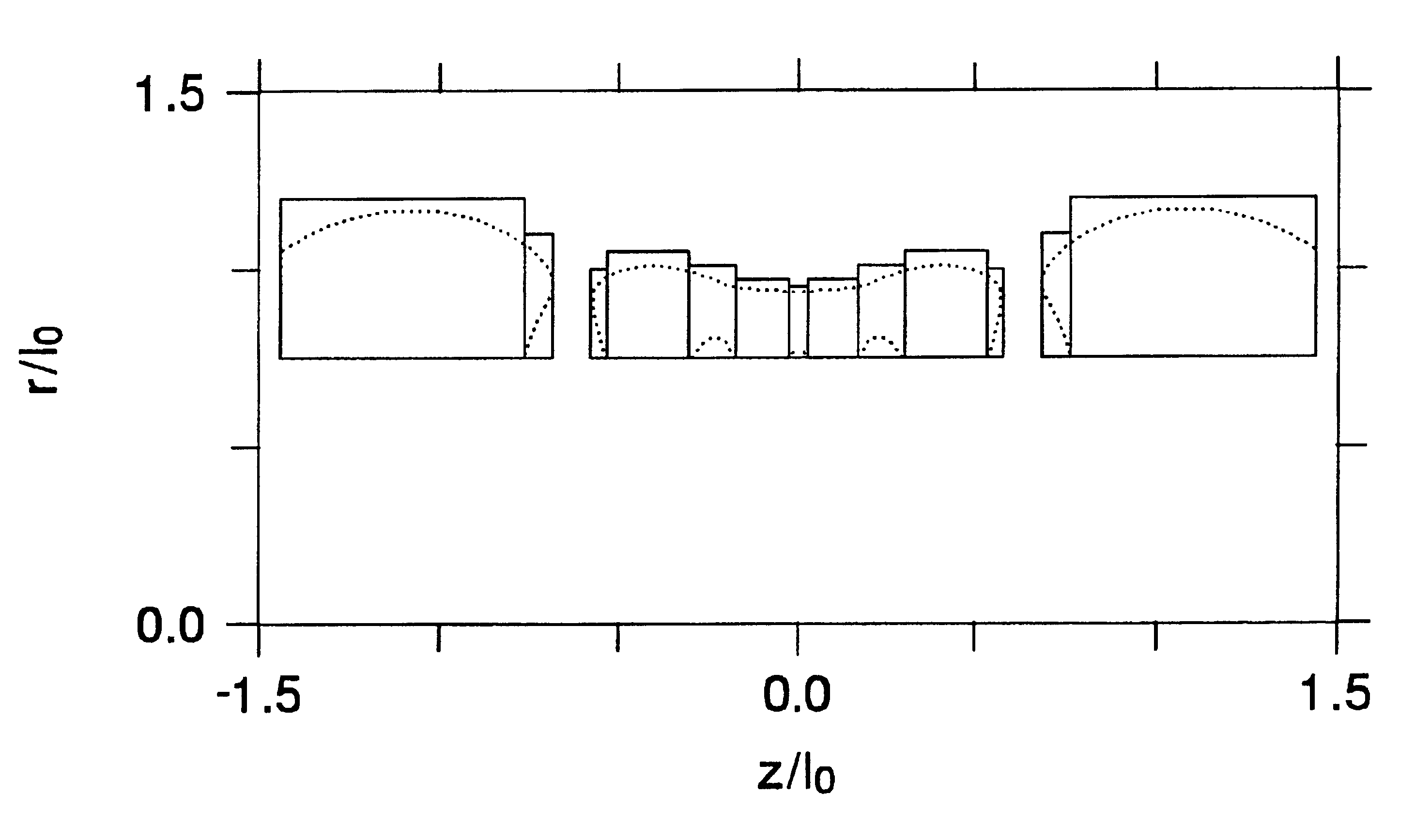
[0060]In order to illustrate the optimization method, I apply it to two different examples. First I compute the minimum volume coil arrangement for a magnet that is comparable to a design proposed in the seminal work M. W. Garrett, “Thick cylindrical coil systems for strong magnetic fields with field or gradient homogeneities of the 6th to 20th order,” J. Appl. Phys., vol. 38, no. 6, pp. 2563-2586, 1967 (“Garrett”). In this paper, Garrett gives numerous coil arrangements that generate uniform fields. However, these arrangements are not optimized in any systematic manner. I choose one simple example and demonstrate how my method can lead to an arrangement with the same external geometry, current density magnitude, field strength and homogeneous volume, but with a significantly smaller coil volume. I also consider varying the current density magnitude and show how to minimize the power consumption for resistive coils. As a second example, I minimize the coil vo...


PUM


Abstract

A computer-implemented method for optimizing the design of an electromagnetic coil arrangement that generates a uniform magnetic field in a desired region, with the electromagnetic coil arrangement having a number of coils and a shape defined by r and z, where r is the radial coordinate of a cylindrical coordinate system having (r, z, φ) coordinates, and z is the axial coordinate of the cylindrical coordinate system. The method has an important use for designing superconductive or resistive coil arrangements for MRI systems. The core of the method is to compute a solution to a master equation (25) for a set of parameters lambda_j which define the coil arrangement and the currents needed. An important advantage is that the resultant coil arrangement has a minimum volume, which saves on material, or uses a minimum power.

Description

[0001]This invention relates to methods for designing electromagnetic coil arrangements that generate uniform magnetic fields, and in particular for optimizing electromagnetic coil arrangements for magnetic resonance imaging (MRI) systems.IA. BACKGROUND OF THE INVENTION[0002]Electromagnets with axially symmetric coil arrangements are commonly used for the generation of uniform magnetic fields. By “uniform field” is meant a magnetic field whose intensity over a desired region does not vary more than 100 parts per million (ppm). An important application nowadays is the medical use of MRI where the desired region is often referred to as the imaging region. MRI of a human body or body part requires large magnets. The magnets may be composed of superconductive materials or of resistive materials. A natural design criterion is that the volume of the coils be as small as possible, consistent with a set of prescribed constraints, since the volume of the coils often correlates closely with a...

Claims


Application Information

Patent Timeline
Patent Type & Authority Patents(United States)
IPC IPC(8): G01R33/381G01R33/38
CPCG01R33/381
Inventor JENSEN, JENS
Owner NEW YORK UNIV
Why Eureka
Try Eureka