Apparatus for mounting a stent onto a stent delivery system

a technology of stent and balloon, which is applied in the direction of prosthesis, blood vessels, shaping tools, etc., can solve the problems of stent being accidentally displaced on the balloon, stent re-closure, waste of materials,

a technology of stent and balloon, which is applied in the direction of prosthesis, blood vessels, shaping tools, etc., can solve the problems of stent being accidentally displaced on the balloon, stent re-closure, waste of materials,

US6948223B2Inactive Publication Date: 2005-09-27MEDTRONIC VASCULAR INC

Image

  • Apparatus for mounting a stent onto a stent delivery system
  • Apparatus for mounting a stent onto a stent delivery system
  • Apparatus for mounting a stent onto a stent delivery system

Examples


Embodiment Construction

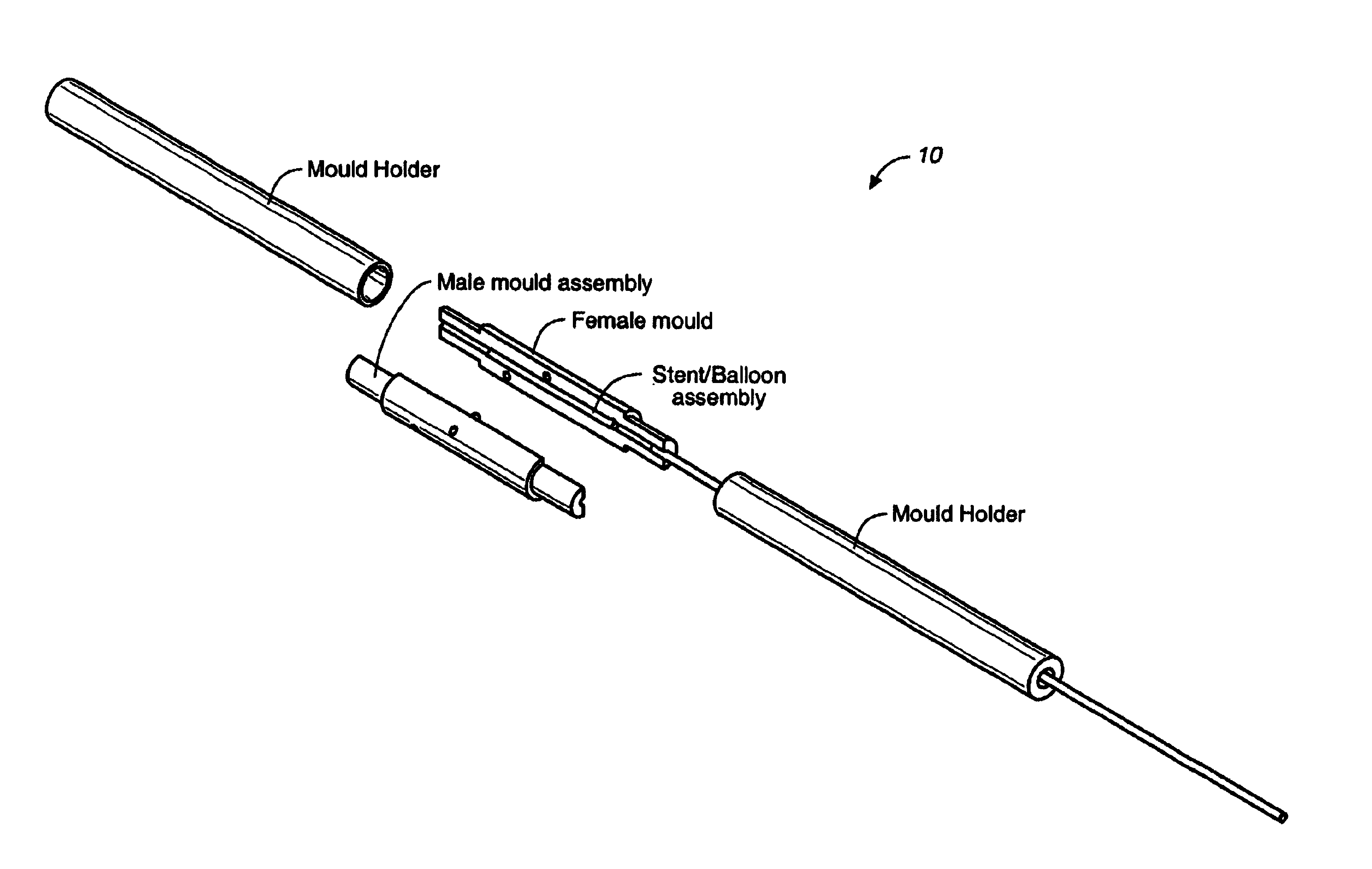
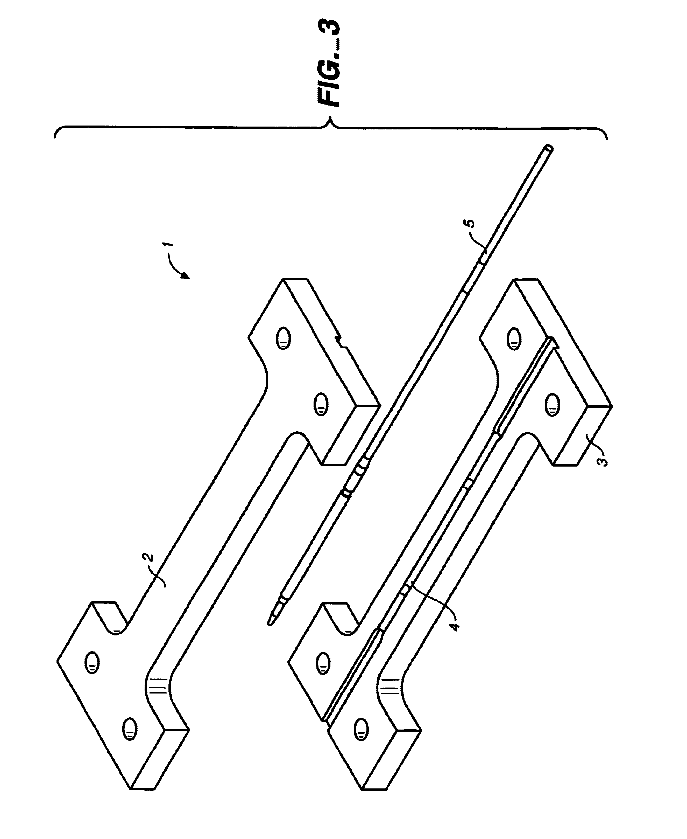
[0031]Referring initially to FIG. 3 and FIG. 4, the mould of the invention is indicated generally by the reference numeral 1 and includes a top portion 2 and a bottom portion 3 provided by splitting the mould along its longitudinal axis. Both the top portion of the mould 2 and the bottom portion 3 of the mould include a cavity or channel 4 for receiving a stent / balloon assembly 5 therein. Channel 4 includes sections 4a and 4b for formation of proximal and distal pillows 27 and 29 respectively.

[0032]In use, a stent balloon assembly is placed in the mould between the top and bottom parties portions 2, 3, then pressurised air is introduced into the balloon interior from the luer-fitting end of the stent / balloon assembly (not shown) and the mould is heated preferably by hot blocks, but any suitable method, including but not limited to hot oil, radiofrequency heating, hot air, infrared or a laser source. Typically, the mould is closed or locked into the closed position pneumatically. Oth...


PUM

PropertyMeasurementUnit
Pressureaaaaaaaaaa

Abstract

The present invention provides a method and apparatus for mounting a stent onto a balloon on a stent delivery system. A stent is then loaded onto the delivery system and the resulting stent / balloon assembly is positioned in a first section of a mould and a second section of the mould is closed onto the first section and locked in place. Pressure is applied to the delivery system through a luer and the mould is heated. The pressure and heat are discontinued and the mould is cooled; this combination of heat and pressure secures the stent to the balloon. The method may include a cooling cycle to help retain the profile of the final stent delivery assembly.

Description

FIELD OF THE INVENTION[0001]The present invention relates to a method and apparatus for mounting a stent onto a balloon on a stent delivery system.BACKGROUND OF THE INVENTION[0002]Intraluminal stenting is useful in treating tubular vessels in the body that are narrowed or blocked and it is an alternative to surgical procedures that intend to bypass such an occlusion. When used in endovascular applications, the procedure involves inserting a prosthesis into an artery and expanding it to prevent collapse of the vessel wall.[0003]Percutaneous transluminal angioplasty (PTCA) is used to open coronary arteries, which have been occluded by a build-up of cholesterol fats or atherosclerotic plaque. Typically, a guide catheter is inserted into a major artery in the groin and is passed to the heart, providing a conduit to the ostia of the coronary arteries from outside the body. A balloon catheter and guidewire are advanced through the guiding catheter and steered through the coronary vasculat...

Claims


Application Information

Patent Timeline
27 Sep 2005
Publication
US6948223B2
IPC
A61F2/06; B29C49/00; B29C35/04; B29C35/08; A61F2/84
CPC
A61F2/958; B29C49/0042; A61F2002/9522; B29C35/045; B29C35/08; B29C2035/043; Y10T29/53917; B29C2035/0838
Inventors
SHORTT, JAMES