Flow measurement device

a flow measurement and flow rate technology, applied in the direction of liquid/fluent solid measurement, instruments, heat measurement, etc., can solve the problems of inability to accurately measure flow rate, inability to accept process variations, and all share a number of problems and limitations, so as to eliminate bubbler pressure sensitivity, improve accuracy, and control flow rate

Inactive Publication Date: 2005-09-27
GRALENSKI NICHOLAS M
View PDF2 Cites 7 Cited by
  • Summary
  • Abstract
  • Description
  • Claims
  • Application Information

AI Technical Summary

Benefits of technology

[0016]In accordance with the foregoing and other objectives, an aspect of the invention provides a flow measurement device that works equally well with gases, liquids or mixtures of gases and liquids. Another aspect of the invention provides greater control over flow rates with very high degree of precision. This is due to the fact that the measurement device eliminates the need for one or more bubblers. Accordingly, this eliminates bubbler pressure sensitivity and the bubbler requirement for exact (and unstable) gas vapor saturation.
[0017]An aspect of the present invention also eliminates the need for a capillary or bypass structure. Since the present measurement device is provided in the flowpath for direct measurement of flow, it advantageously eliminates the introduction of inaccuracies, bypass errors or inaccurate assumptions inherent in a conventional bypass structure.
[0018]Another aspect of the invention provides an internal electric heat source. Because the heat source is internal, the invention does not suffer from any of the heat transfer problems associated with conventional mass flow meters. Since the heat transfer associated with the heater forms the basis of flow measurement, improved accuracy is achieved.

Problems solved by technology

Small process variations, too small to be accommodated by conventional mass flow devices, can result in unacceptable process variations when feature sizes are measured with respect to nanometers.
Although there are a number of variations of these conventional mass flow meters, they all share a number of problems and limitations.
These problems and limitations include, inherent inaccuracies, inherent process variations, maintenance difficulties, cleaning difficulties and inefficient size.
However, the conventional “bypass or capillary” MFM has subtle limitations that increasingly limit its suitability for sophisticated processing.
These changes in heat transfer characteristics affect the correlation between heater energy and temperature differential and reduce the precision of the MFM.
Such temperature difference is undesirable because it introduces an uncertainty in the amount of fluid being heated and thus an uncertainty in the amount of fluid flow.
The above limitations apply to gaseous flow.
For liquid flow, additional complications impose limitations on the accuracy of conventional methods of mass flow measurement.
The introduction of two phases into the capillary significantly and unpredictably alters the correlation between heater energy and temperature differential.
Under these circumstances, the flow signals become totally unreliable.
The amount of liquid used is frequently very small which makes accurate measurement difficult.
Obviously, accurate control of a bubbler is no simple task.

Method used


Image

  • Flow measurement device
  • Flow measurement device
  • Flow measurement device

Examples


working example

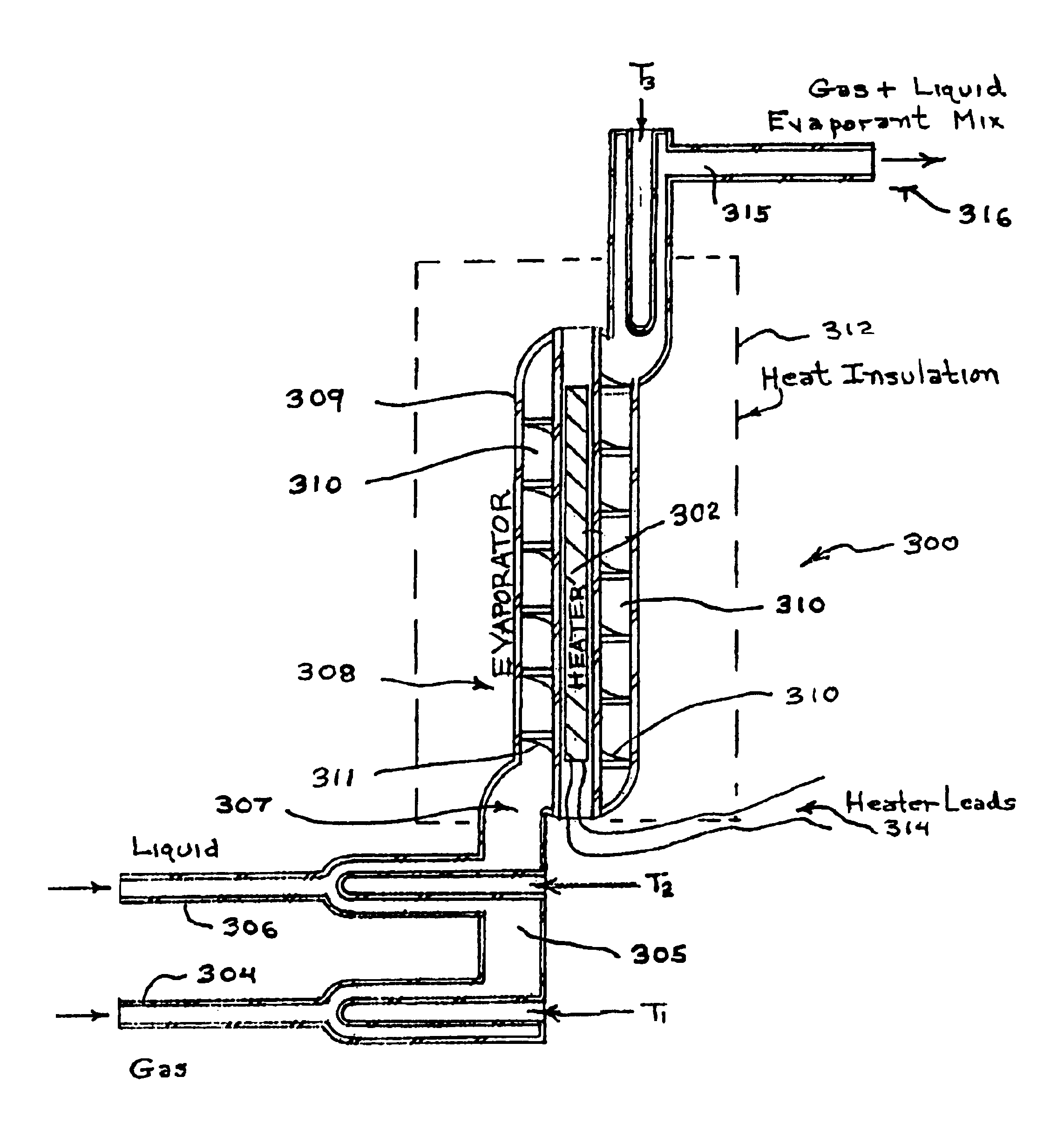
[0031]When the device of FIG. 3 is used in its simplest form (measuring gas flow only), the electrical power required (E) is equal to the product of specific heat (S.H.) times the temperature change produced by the device (ΔT) times the gas flow rate (G)

Or: E⁢ ⁢(Watts)=⁢S.H. ⁢(Joules⁢ ⁢per⁢ ⁢gram⁢ ⁢per⁢ ⁢°⁢ ⁢C.)⁢Δ⁢ ⁢T⁢ ⁢(°⁢ ⁢Centigrade)×⁢G⁢ ⁢(Grams⁢ ⁢per⁢ ⁢second)×

Or:

E=S.H.×ΔT×G

[0032]For argon gas (commonly used), SH=0.523

[0033]Any ΔT can be chosen which doesn't damage apparatus or gas. A convenient ΔT may be 85° C.

[0034]In that case,

E=0.523×85×G=44.455G

Or, G=0.0225E

[0035]Thus, measurement of the input wattage is a direct indication of the gas flow. It may be more convenient to select an output temperature before hand as part of the process. The selection would be based on one not damaging to apparatus or gas, maximization of measurement signal, minimization of delivery tube heating etc. While such selection sounds complicated, it is instead a means of optimizing process conditions ...


PUM

PropertyMeasurementUnit
pressureaaaaaaaaaa
humidityaaaaaaaaaa
pressureaaaaaaaaaa

Abstract

An improved flow measurement device is provided in a flow path for direct measurement of flow. An internal heat source solves the problem of heat transfer in conventional mass flow meters. The heat transfer associated with the internal heater forms the basis of flow measurement, and improved accuracy is achieved. The flow measurement device advantageously eliminates the introduction of inaccuracies, bypass errors, or inaccurate assumptions that are inherent in a conventional bypass structure. The present measurement device eliminates the need for one or more bubblers and thus overcomes bubbler pressure sensitivity and the bubbler requirement for exact (and unstable) gas vapor saturation of conventional flow measurement. The flow measurement device works equally well with gases, liquids or mixtures of gases and liquids and provides greater control over flow rates with very high degree of precision.

Description

RELATED APPLICATION[0001]This application is based on U.S. provisional patent application Ser. No. 60 / 396,216 entitled, Flow Measurement Device filed Jul. 16, 2002.BACKGROUND[0002]1. Field of the Invention[0003]The field of the invention generally relates to techniques for precisely measuring the flow rates of gases and liquids and mixtures thereof. In particular, the field of the invention relates to a flow measurement device positioned in a flow path for measuring liquids and gases, or a mixture thereof that achieves a previously unattainable degree of precision. Positioning of the flow measurement device in the flow path eliminates the complexity and inaccuracies inherent in a conventional bypass structure and enables precise real time control of process parameters.[0004]2. Background of Related Art[0005]Accurate flow rates of gases and liquids are of wide-ranging interest in our economy. In particular, as semiconductor feature sizes shrink to atomic scales, it is essential that ...

Claims


Application Information

Patent Timeline
Patent Type & Authority Patents(United States)
IPC IPC(8): G01F1/68G01F5/00G01K17/06G01K17/00G01F1/684G01F1/74
CPCG01F1/6842G01F1/74
Inventor GRALENSKI, NICHOLAS M.
Owner GRALENSKI NICHOLAS M
Why Eureka
Try Eureka