Methods for ultrasonic inspection of spot and seam resistance welds in metallic sheets and a spot weld examination probe system (SWEPS)

a technology of spot and seam resistance welds and probe systems, which is applied in the direction of instruments, heat measurement, specific gravity measurement, etc., can solve the problems of inability to adapt to the features of measurement, inability to make portable, and inability to carry around

Inactive Publication Date: 2005-09-27
APPLIED METRICS
View PDF16 Cites 56 Cited by
  • Summary
  • Abstract
  • Description
  • Claims
  • Application Information

AI Technical Summary

Benefits of technology

[0010]A “pencil like” probe having an interchangeable tip is used to perform inspections of spot weldments in sheet metal components. This probe can be hand manipulated for scanning purposes, or can be attached to some mechanical scanners. The hand manipulation permits the examination of spot welds that are in locations with minimal or tight clearances, in locations on complex surfaces and orientations, and in locations where access is limited and complex. The probe is elongated to allow the user some flexibility in gripping the probe.
[0013]These features when combined in this fashion, result in a feasible and portable scanner that is capable of making a broad range of nondestructive spot weld measurements without the need for an immersion tank.

Problems solved by technology

Although there are many ultrasonic transducers and scanners in the prior art none has adapted to the features needed to measure the unique parameters and topology encountered in spot welds.
The immersion tank must fit the largest part and, as a result is usually too large to be made portable.
The water in the tank requires conditioning and adds to the size of the system.

Method used


Image

  • Methods for ultrasonic inspection of spot and seam resistance welds in metallic sheets and a spot weld examination probe system (SWEPS)
  • Methods for ultrasonic inspection of spot and seam resistance welds in metallic sheets and a spot weld examination probe system (SWEPS)
  • Methods for ultrasonic inspection of spot and seam resistance welds in metallic sheets and a spot weld examination probe system (SWEPS)

Examples


Embodiment Construction

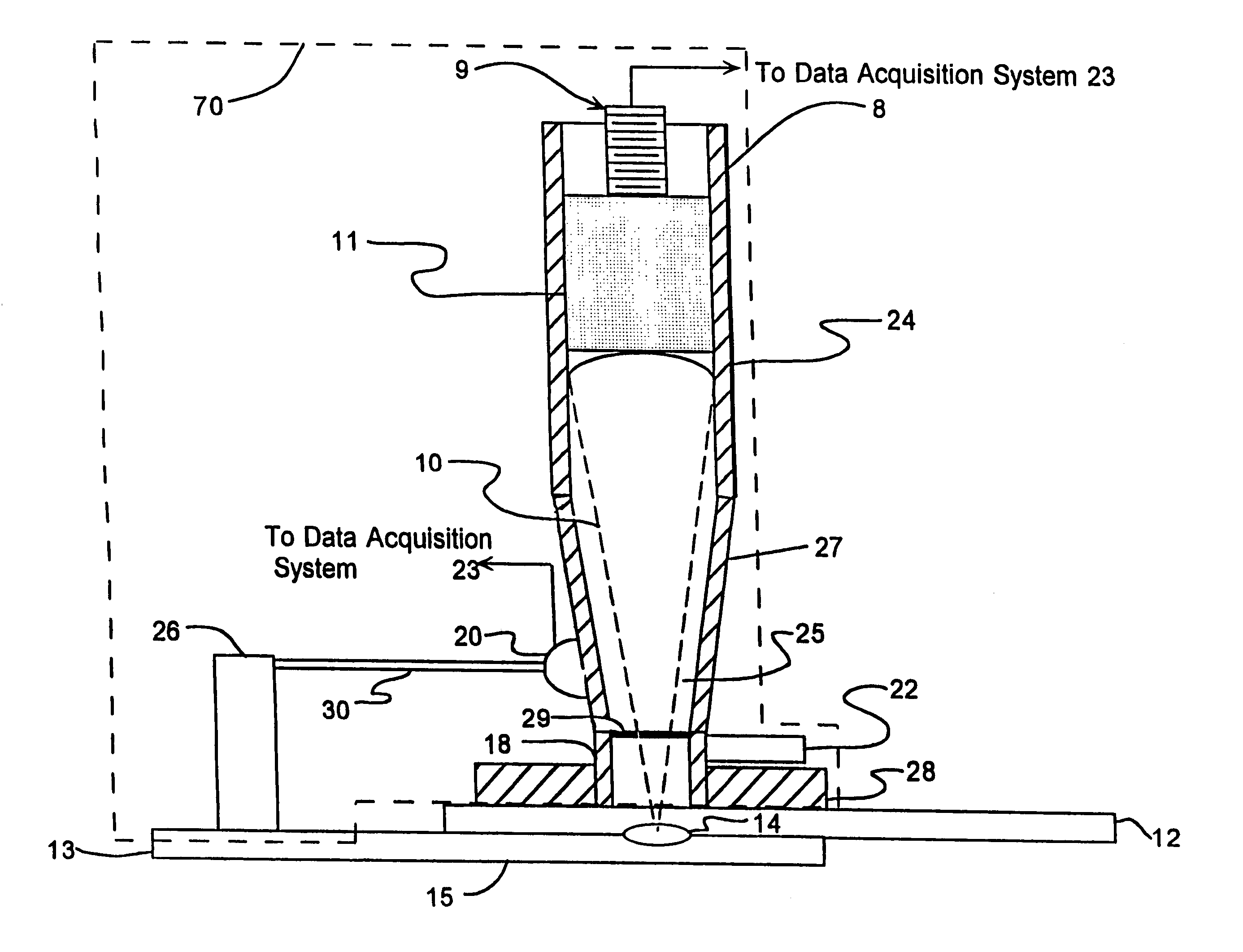
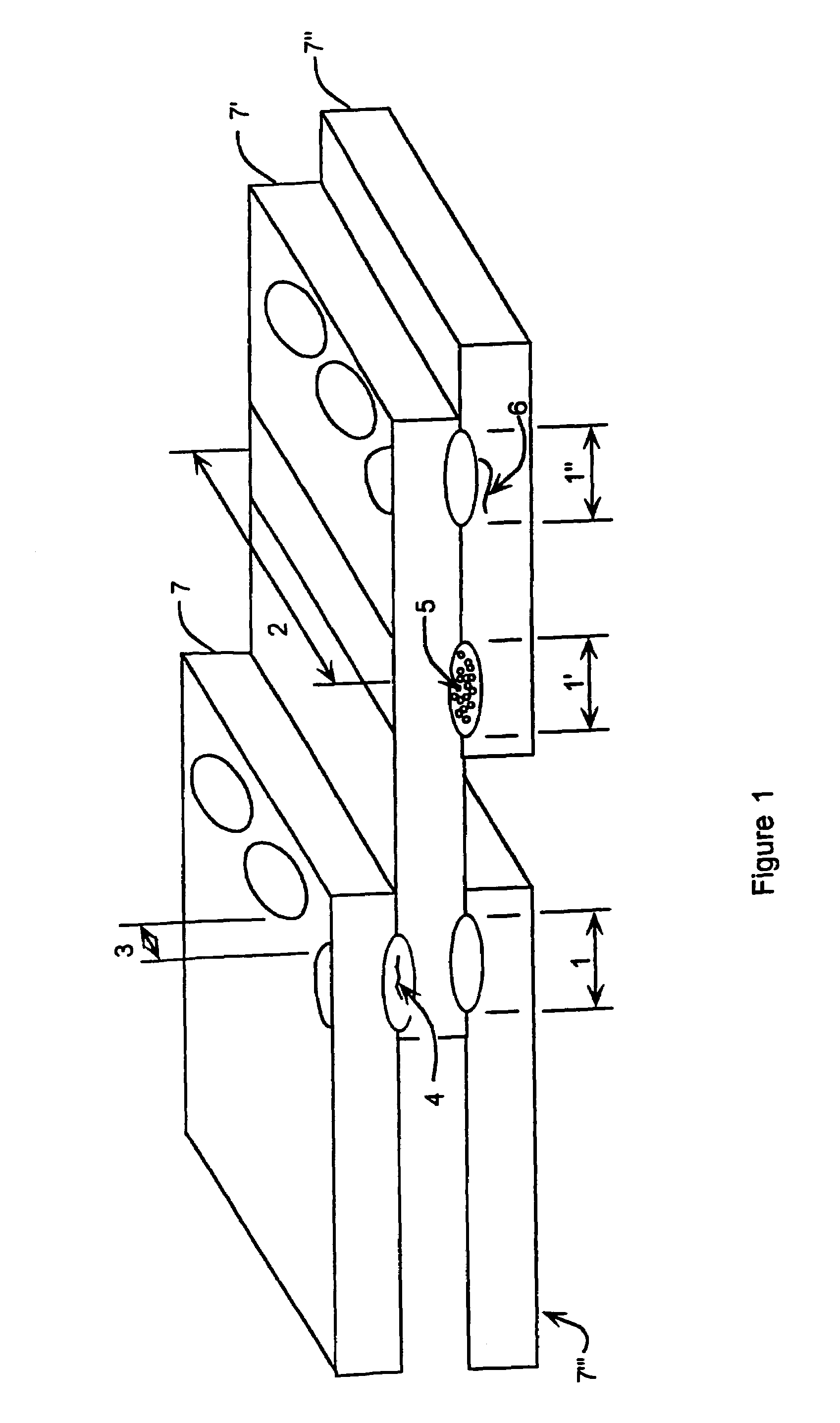
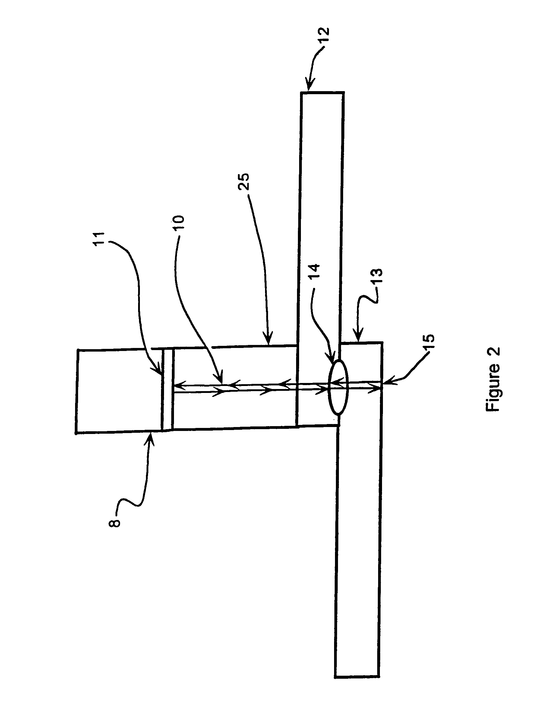
[0023]The spot and seam type welds used to attach two or more sheets, or plates, of metal together are addressed, as shown, in FIGS. 1, 2, 3, 4, 6 and 7 where the measurement of fused weldment dimensions is one of the objectives of the present invention. Since ultrasonic waves penetrate a fused weld zone, the method of the present invention is capable of non-destructively, in open-air, determining the length of a continuous fused section(s) which easily relate to weld strength without immersing the material being tested in water or another liquid. Additionally, ultrasound is sensitive to common weld defects which will be seen below.

[0024]The present invention uses a focused ultrasonic beam with a means for encoding transducer movement to measure the length and penetration of a fused weldment. The present invention uses an ultrasonic transducer selected to provide a signal with a frequency that will be transmitted by properly fused weldments and blocked, or refelcted by weldment defe...


PUM

PropertyMeasurementUnit
frequencyaaaaaaaaaa
bevel angleaaaaaaaaaa

Abstract

An external focused ultrasonic beam, non-destructive, open-air, inspection method of sheet metal spot and seam weldments using a probe in combination with motion measurement of the probe over the weldments during inspection without immersion of the material. Reflected ultrasonic waves are received and signals produced and processed or displayed as A-scan, B-scan and C-scan images that are easily recognized. An A-Scan is based on the time-of-flight difference between the outer surface, the weldment and inner and opposite surfaces of the component. B-scan and C-scan indicate the degree of weld fusion and provide data relative to fused thickness and defects sheet metal or welds. A special purpose scanner that enables ultrasonic examination welds. Scanner is pencil like ultrasonic probe with bearing face and position sensing device disposed adjacent a weld position. Scanner collects data for method to determine various characteristics of welded items.

Description

[0001]This application claims priority from U.S. Provisional Application Ser. No. 60 / 354,688 filed Feb. 6, 2002, and is a continuation of utility patent application having Ser. No. 10 / 361,714 and filed on Feb. 6, 2003, now abandoned.BACKGROUND OF THE INVENTION[0002]1. Field of the Invention[0003]This invention relates to a specialized scanner and method of inspecting the integrity of spot and seam welds and more particularly it relates to an ultrasonic, nondestructive method of inspecting spot and seam welds.[0004]2. Description of the Prior Art[0005]Heretofore, the inspection of spot and seam welds has been performed using visual, radiographic and ultrasonic methods; as described in the Nondestructive Testing Handbook (Metals Handbook, 9th Edition, Volume 17, “Nondestructive Evaluation and Quality Control”, ASM International, Metals Park, Ohio, September, 1989, pg. 335) and the Metals Handbook (Nondestructive Testing Handbook, 2nd Edition, Volume 7. “Ultrasonic Testing”, American S...

Claims


Application Information

Patent Timeline
Patent Type & Authority Patents(United States)
IPC IPC(8): G01N3/00G01N29/07G01N29/24G01N29/265
CPCG01N3/00G01N29/0645G01N29/07G01N29/2456G01N29/265G01N2203/0296G01N2291/0234G01N2291/0237G01N2291/02854G01N2291/044G01N2291/2672G01N2291/2675
Inventor FLEMING, MARVIN F.CLARK, JACK P.
Owner APPLIED METRICS
Why Eureka
Try Eureka