Hammer

a technology of electric hammer and hammer head, which is applied in the direction of manufacturing tools, percussive tools, portable drilling machines, etc., can solve the problems of hammer seals that are easily worn between the ram and the spindle, serious damage to the hammer, and are necessarily operated in very dusty and dirty environments. , to achieve the effect of simple and easy-to-assemble structur

Inactive Publication Date: 2005-09-27
BLACK & DECKER INC
View PDF52 Cites 26 Cited by
  • Summary
  • Abstract
  • Description
  • Claims
  • Application Information

AI Technical Summary

Benefits of technology

[0014]The present invention aims to provide a beatpiece guiding and damping arrangement which solves all of the problems discussed and which results in a relatively simple and easy to assemble structure.

Problems solved by technology

Hammers are necessarily operated in very dusty and dirty environments.
If dust gets into the spindle of the hammer it can cause abrasion between the reciprocating parts and, in particular, can cause seals between the ram and the spindle to become worn.
Wearing of the seal around the ram will cause the air cushion to deteriorate, which will eventually lead to impacts occurring between the beatpiece and the ram which can seriously damage the hammer.
Therefore, a further issue in the longevity of the working life of a hammer is its sealing against dust.
The reciprocation of parts within the spindle can draw dust rearwardly inside the hammer spindle, where damage can be caused.
The arrangement in U.S. Pat. No. 4,476,941 has a problem with dust ingress, in particular during periods when a tool or bit is removed from the tool holder of the hammer, into the portion of the forward sleeve where the beatpiece is guided.
This problem is exacerbated by the pumping nature of the increased diameter portion of the beatpiece which is guided within the second sleeve.
The small amount of axial support for the first sleeve which is mounted between spindle parts, along with usual tolerance limitations for component parts could lead to a reduced accuracy of axial guiding of the beatpiece by the sleeves.
The design in U.S. Pat. No. 4,476,941 results in a complicated multi-part spindle, beatpiece guiding and damping structure, with the associated assembly problems and cost implications.
The arrangement in DE196 21 610 overcomes some of the problems discussed above, but still has the disadvantage of a relatively complex three part spindle arrangement, having sleeves for beatpiece guiding mounted and guided in different spindle parts.
Again the usual tolerance issues between spindle parts can reduce the accuracy with which the beatpiece is guided and complicates the sealing of dust from the inside of the spindle.
Again the design in DE196 21 610 has a complicated multi-part spindle, beatpiece guiding and damping structure, with the associated assembly problems and cost implications.

Method used


Image

  • Hammer
  • Hammer
  • Hammer

Examples


Embodiment Construction

[0035]A preferred embodiment according to the present invention will be described hereinafter with reference to the attached drawings.

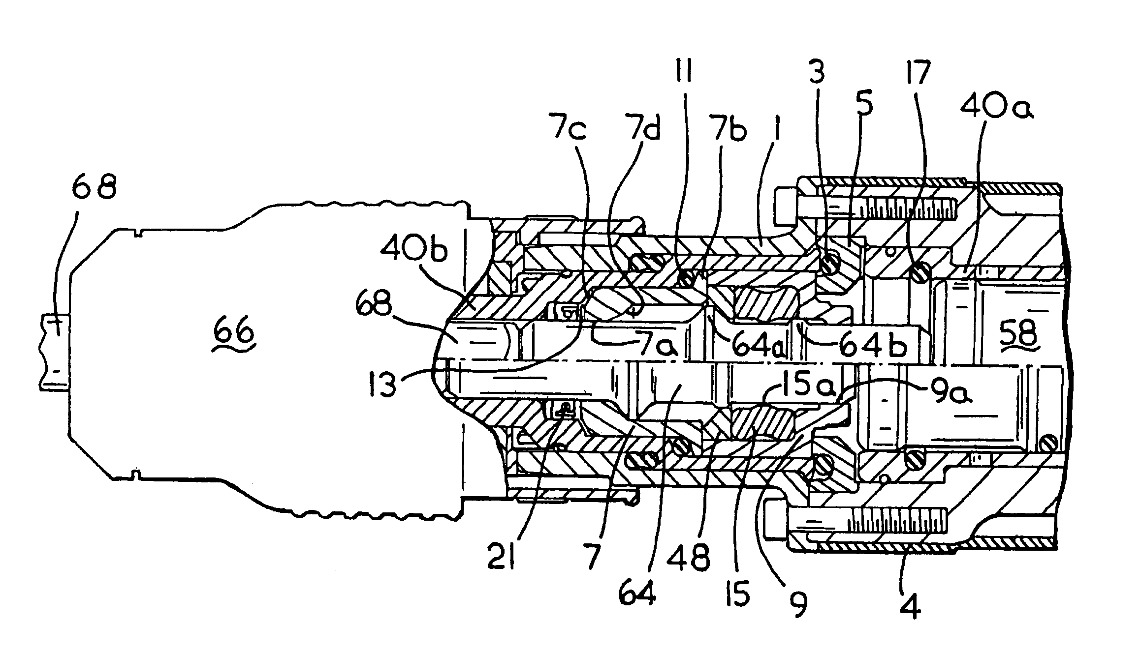
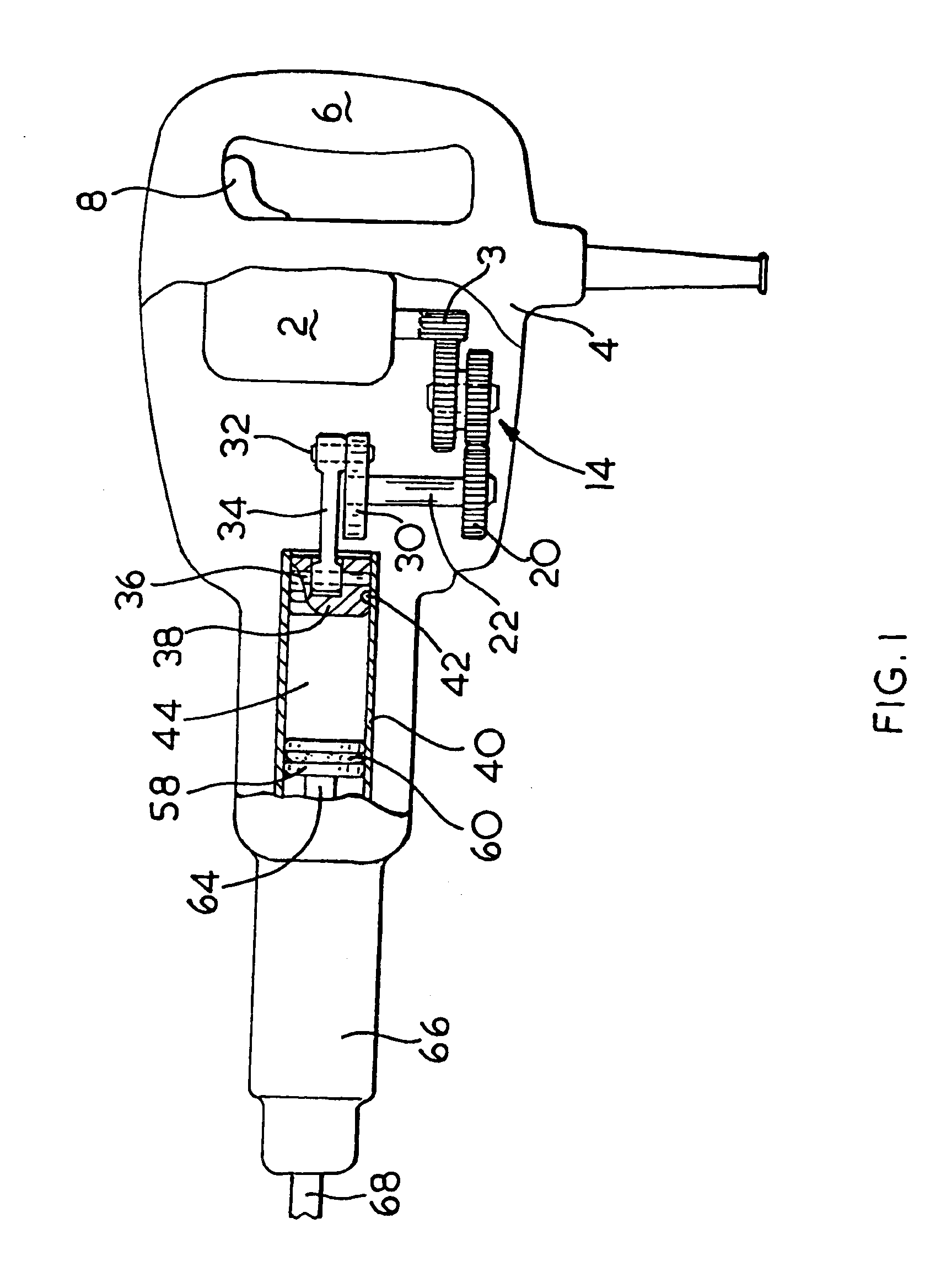
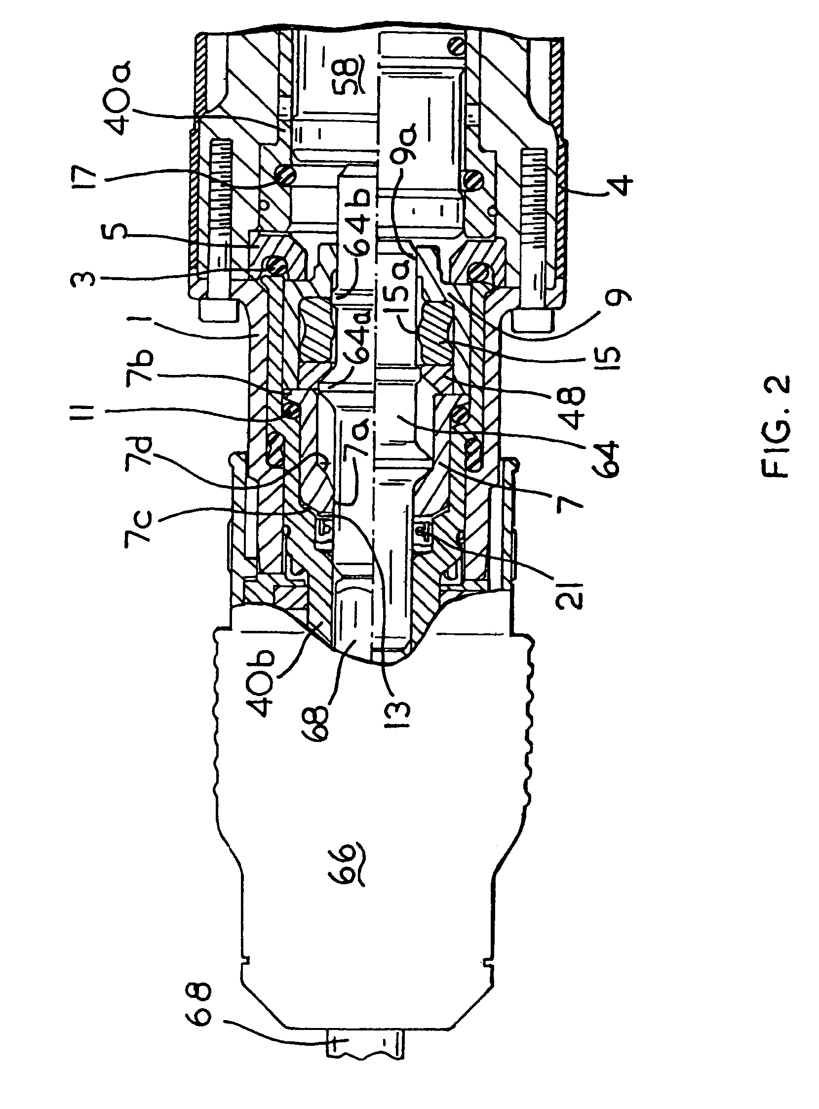
[0036]The hammer shown in FIG. 1 comprises an electric motor (2), an intermediate gear arrangement (14, 20) and a crank drive arrangement (30-36) which are housed within a metal gear housing (not shown) surrounded by a plastic housing (4). A rear handle housing incorporating a rear handle (6) and a trigger switch arrangement (8) is fitted to the rear of the housing (4). A cable (not shown) extends through a cable guide (10) and connects the motor to an external electricity supply. Thus, when the cable is connected to the electricity supply and the trigger switch arrangement (8) is depressed the motor (2) is actuated to rotationally drive the armature of the motor.

[0037]A hollow cylindrical spindle (40) is mounted within the hammer housing. A piston (38) and a ram (58) are located within the spindle. The motor (2) drives a crank plate (30) via an inter...


PUM

PropertyMeasurementUnit
diameteraaaaaaaaaa
internal diameteraaaaaaaaaa
axial movementaaaaaaaaaa

Abstract

An electrically powered hammer comprising a hollow spindle within which spindle is reciprocatingly mounted a piston, a ram, a beatpiece having an increased external diameter mid-portion and located within the spindle between the ram and the tool or bit, a two part sleeve arrangement located within the spindle and including an increased internal diameter mid-portion for receiving the increased external diameter portion of the beatpiece and a reduced internal diameter forward and rearward portion for guiding the forward and rearward ends respectively of the beatpiece and where the sleeve arrangement includes a forward sleeve and a rearward sleeve which are both guided with tight radial tolerances and with a slight axial play within and by the spindle and the forward axial movement of the forward sleeve is limited by a reduced diameter portion of the spindle and the forward axial movement of the rearward sleeve is limited by the forward sleeve.

Description

CROSS-REFERENCE TO RELATED APPLICATIONS[0001]This application is a continuation of U.S. patent application Ser. No. 10 / 092,754 filed on Mar. 7, 2002 now U.S. Pat. No. 6,732,815. This application claims the priority of U.K. Patent Application No. GB 0105547.4, filed Mar. 7, 2001 and U.K. Patent Application No. GB 0125749.2, filed Oct. 26, 2001, the contents of which are incorporated herein by reference.BACKGROUND OF THE INVENTION[0002]1. Field of the Invention[0003]This invention relates to electric hammers having an air cushion hammering mechanism.[0004]2. Description of the Related Art[0005]Such hammers will normally have a housing and a hollow cylindrical spindle mounted in the housing. The spindle allows insertion of the shank of a tool or bit, for example a drill bit or a chisel bit, into the front end thereof so that it is retained in the front end of the spindle with a degree of axial movement. The spindle may be a single cylindrical part or may be made of two or more cylindri...

Claims


Application Information

Patent Timeline
Patent Type & Authority Patents(United States)
IPC IPC(8): B25D17/08B25D17/24B25D11/00B25D17/00B25D17/06B25D11/06B25D11/12
CPCB25D11/062B25D11/125B25D17/06B25D17/088B25D17/24B25D17/20B25D2211/003B25D2250/191B25D2250/365B25D2217/0065
Inventor HANKE, ANDREASBUCHHOLZ, ACHIMBERNHART, RALF
Owner BLACK & DECKER INC
Why Eureka
Try Eureka