
Locking hook bolt and method for using same

a technology of locking hooks and bolts, which is applied in the direction of screws, threaded fasteners, ways, etc., can solve the problems of reducing the potential for vehicles to override the system, and achieve the effects of reducing the number of premature releases, discharging the energy of errant vehicles, and strong connection to support posts

Inactive Publication Date: 2005-09-27
TEXAS A&M UNIVERSITY
View PDF177 Cites 49 Cited by
  • Summary
  • Abstract
  • Description
  • Claims
  • Application Information

AI Technical Summary

Benefits of technology

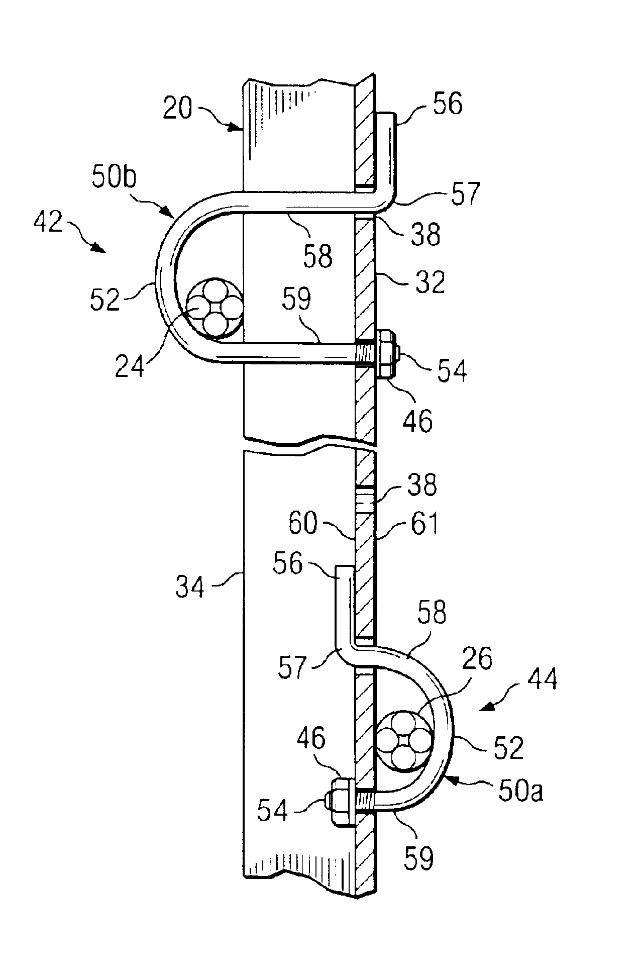
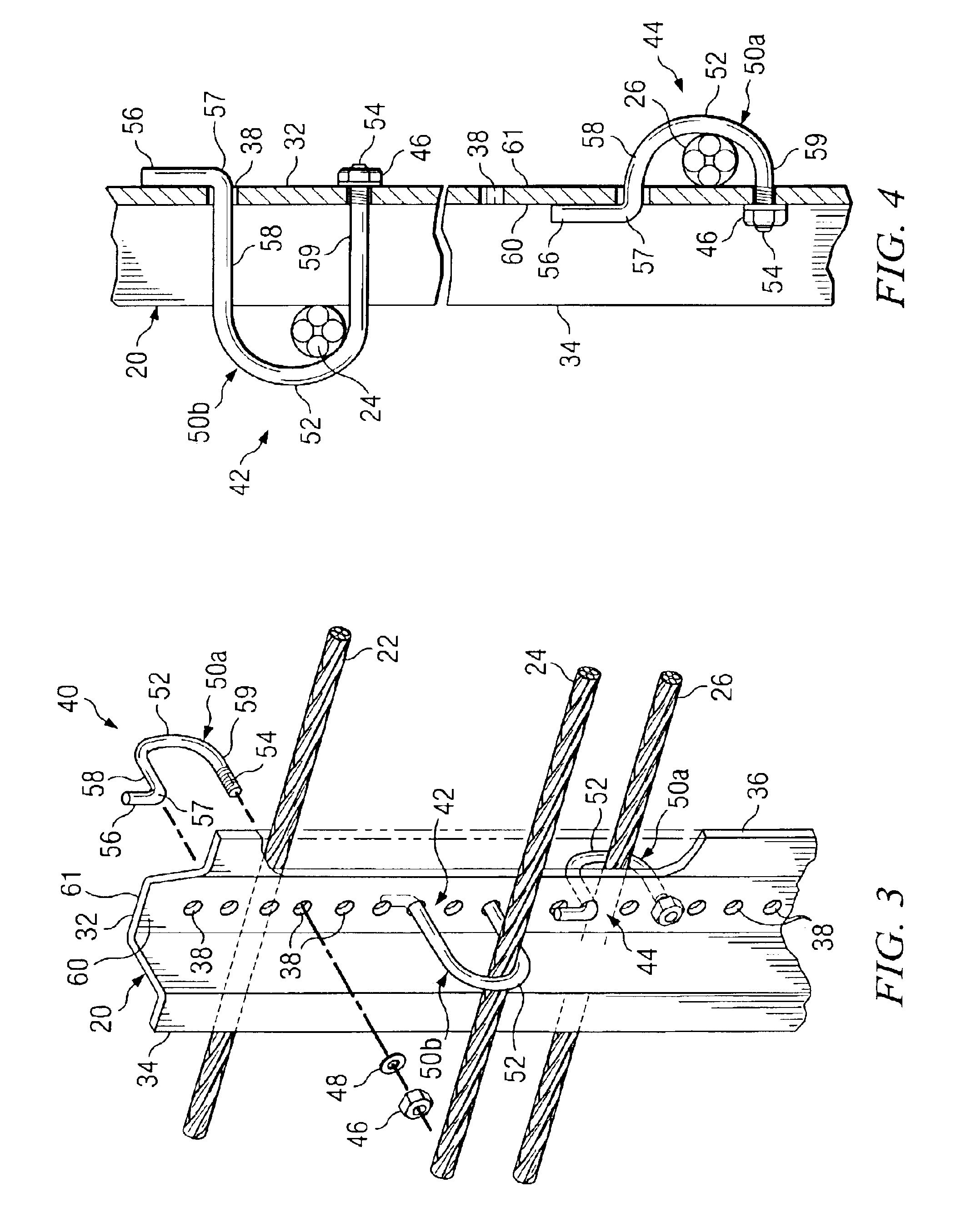
[0007]A technical advantage of particular embodiments of the present invention includes the ability to create a stronger connection to support posts due to the shape of the locking hook bolt along with its threaded portion, which secure both ends of the locking hook bolt to the support post. This permits the strength of the post to be fully utilized to dissipate the energy of an errant vehicle before the release of the wire ropes from the support post.
[0008]Another technical advantage of particular embodiments of the present invention is a reduction in the number of premature releases of wire ropes upon impact by errant vehicles. This allows more of the load from an errant vehicle to be transmitted to more adjacent support posts, spreading the load among more support posts and, thus, decreasing system deflections upon impact by errant vehicles.
[0009]Yet another technical advantage of particular embodiments of the present invention is that the strength of the locking hook bolt can be adjusted to match the strength of the support post. This can be accomplished by varying the material properties or diameter of the steel round stock from which the locking hook bolt is fabricated, and / or adjusting the length of the locking portion extending from the second leg of the locking hook bolt. In this manner, the strength of the post may be more fully utilized, but the cable is allowed to release from the support post as the capacity of the post is reached. This not only prevents the premature release of the cable from the support post, but also prevents the cable from being pulled down as the support post deforms, thus reducing the potential for vehicles to override the system.

Problems solved by technology

This not only prevents the premature release of the cable from the support post, but also prevents the cable from being pulled down as the support post deforms, thus reducing the potential for vehicles to override the system.

Method used


Image

  • Locking hook bolt and method for using same
  • Locking hook bolt and method for using same
  • Locking hook bolt and method for using same

Examples


Embodiment Construction

[0018]In accordance with particular embodiments of the present invention, a locking hook bolt and method for using the same are provided. The locking hook bolt allows cable to be securely fastened to a support post in a guardrail system that is used to restrain errant vehicles to a roadway, such that the overall instances of premature release and system deflections are reduced. This is due, at least in part, to the fact that the shape of the bolt, in connection with its threaded section, serves to create a stronger connection to the support posts.

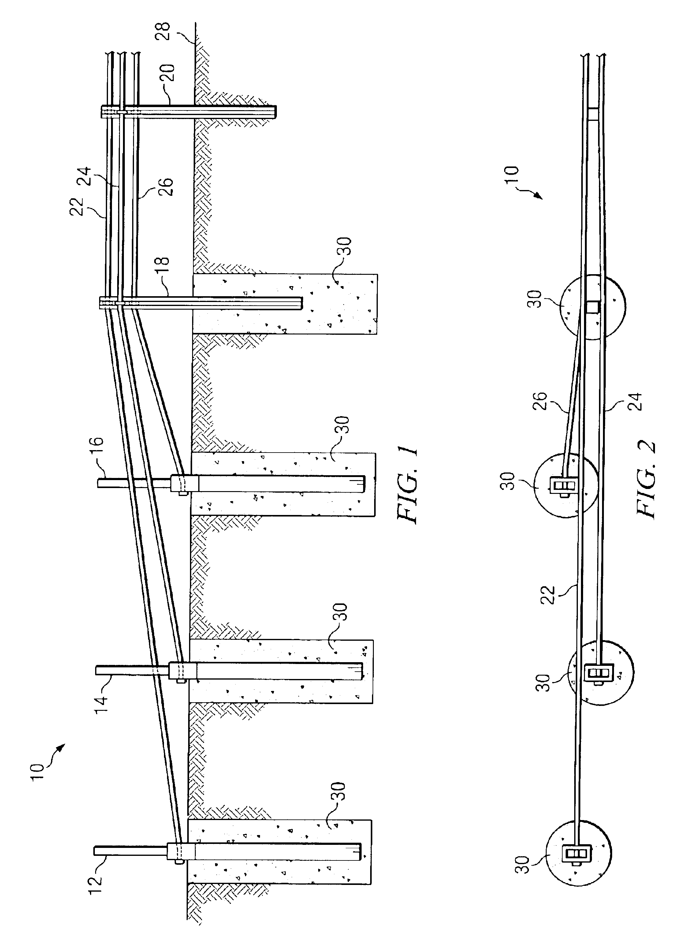
[0019]FIG. 1 illustrates a portion of a cable guardrail system 10, in accordance with a particular embodiment of the present invention, in which a plurality of locking hook bolts are used to secure a plurality of cables to the support posts of the guardrail assembly. Cable guardrail system 10 may be installed adjacent to a roadway to protect vehicles, drivers, and passengers from various obstacles and hazards and to prevent vehicles from le...


PUM


Abstract

A locking hook bolt, which may be used for securing cable to support posts in guardrail assemblies, and a method for using the same are provided. The locking hook bolt includes a first leg, a second leg, and an arcuate portion coupling the first and second legs such that the second leg extends generally parallel with, and spaced apart from, the first leg. A locking portion configured to engage a support post extends from, and forms an angle of approximately 90 degrees with, the second leg. The first leg of the locking hook bolt includes a threaded portion opposite the arcuate portion.

Description

RELATED APPLICATIONS[0001]The present application is a continuation-in-part of U.S. Ser. No. 10 / 355,601, filed Jan. 30, 2003, entitled Cable Guardrail Release System. The present application claims the benefit of U.S. Provisional Application Ser. No. 60 / 380,549 filed May 14, 2002 entitled Locking Hook Bolt, U.S. Provisional Application Ser. No. 60 / 380,632 filed May 15, 2002, entitled Cable Guardrail Terminal, and. U.S. Provisional Application Ser. No. 60 / 353,000 filed Jan. 30, 2002, entitled Cable Guardrail Terminal.TECHNICAL FIELD OF THE INVENTION[0002]The present invention relates in general to field of bolt assemblies and, in particular, to a locking hook bolt and a method for using the same.BACKGROUND OF THE INVENTION[0003]Guardrail systems are commonly used along highways and other roadways to prevent or reduce damage to vehicles and their occupants when they leave the road. These guardrails are designed to redirect the vehicle back onto the roadway and absorb the energy from t...

Claims


Application Information

Patent Timeline
IPC IPC(8): F16B2/02F16B2/06
CPCF16B2/065E01F15/06
Inventor ALBERSON, DEAN C.MAUER, IV, FREDERICKBULLARD, JR., D. LANCEBLIGH, ROGER P.BUTH, C. EUGENE
Owner TEXAS A&M UNIVERSITY
Learn More