
Dual mode transmitter/receiver and decoder for RF transponder units

a transponder unit and dual-mode technology, applied in the field of rfid receiver system, can solve the problems of not standardizing the various rf-id applications and complex known devices

Inactive Publication Date: 2005-09-27
X CYTE
View PDF150 Cites 109 Cited by
  • Summary
  • Abstract
  • Description
  • Claims
  • Application Information

AI Technical Summary

Benefits of technology

[0024]Various advantages of spread spectrum communications may be obtained according to the present invention. First, a receive may be sensitive to the presence of interfering signals in the environment, especially frequency stationary sources, and avoid employing these frequencies, or ensuring that each tag is interrogated for each portion of a complete cycle outside an interference scope. Further, by providing a common band broader than necessary for any one transponder system, a number of interrogation systems may share the same band and environment with low risk of interference. So long as the interrogation sequences are non-overlapping, or uncorrelated, operation will be generally reliable, without need for coupling the interrogation systems. Of course, the interrogation systems may also be coupled, to ensure that there is little or not interference.
[0028]By allowing a modulated backscatter radio-frequency identification tags to coexist in an environment with surface acoustic wave identification tags, the present invention simplifies system operation with differing tag types and allows a system to be established with a future change in preferred tag type, without redundant or incompatible equipment.
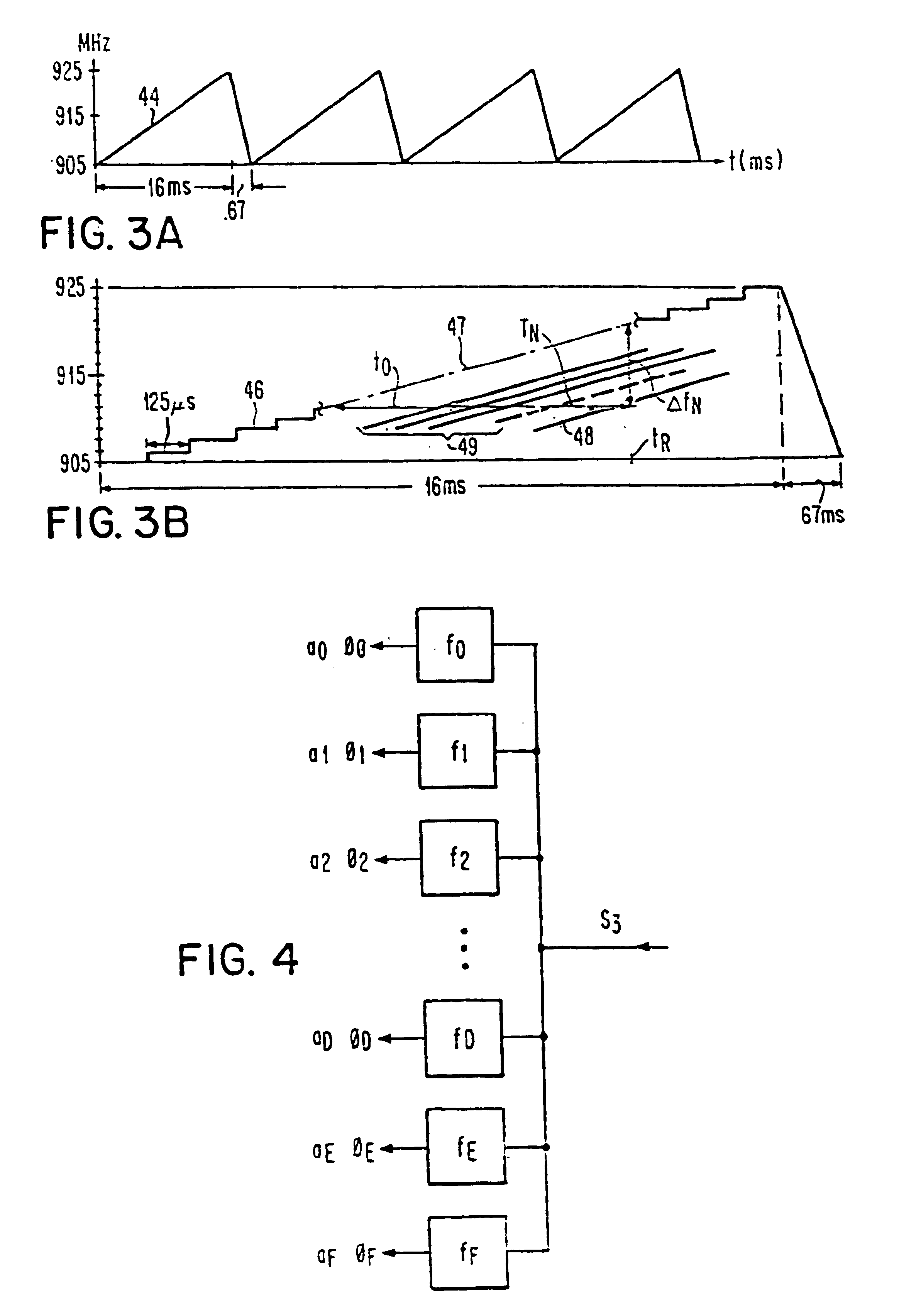
[0030]Of particular note in the present invention, the “carrier” frequency is not stationary, and therefore the receiver is capable of receiving digitally modulated backscatter signals which are immediately modulated and retransmitted, without substantial delay, as well as reradiated radio frequency signals in which the encoding is presented as one or more substantial delays of a retransmitted derivative of the excitation signal, e.g., from a SAW-based RF tag. In the latter case, by retuning the excitation signal periodically or continuously, the delayed signals may be detected, which would be difficult or impossible if the excitation signal remained at the same frequency. On the other band, this non-stationary excitation signal requires compensation before a digitally modulated backscatter signal may be detected. Thus, the present invention provides a multiprotocol tag reader, allowing different types of tags to be reliably identified.
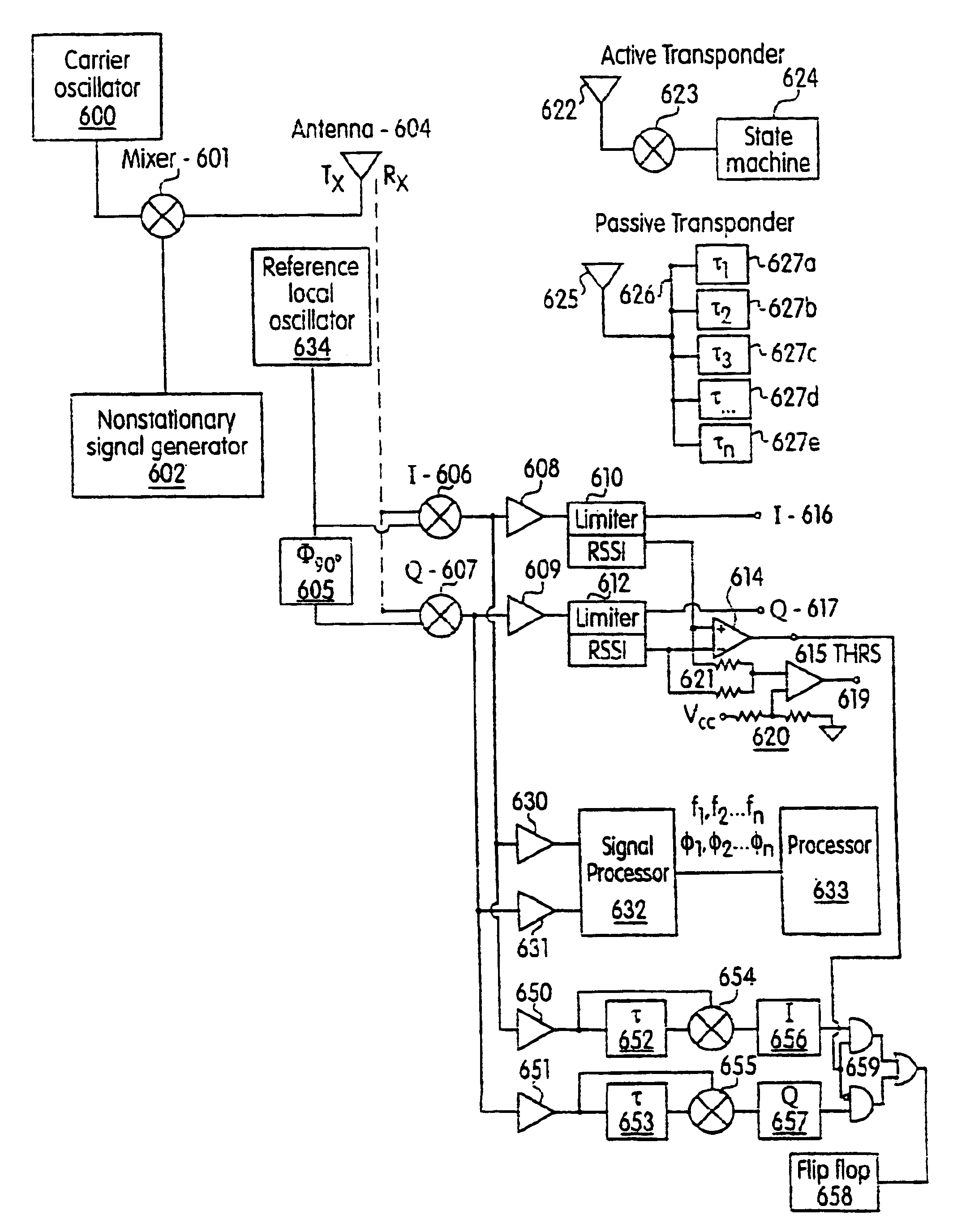
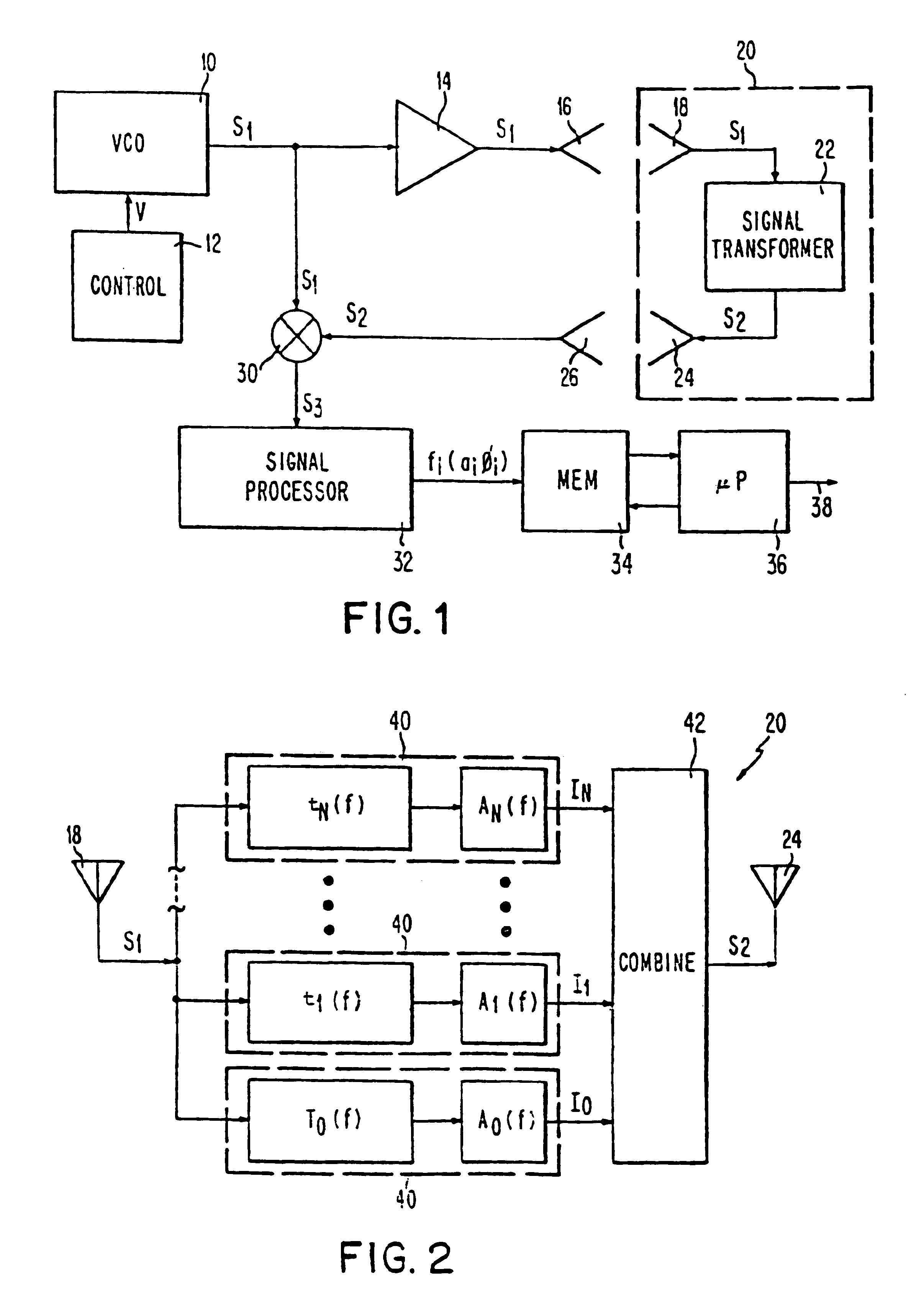
[0033]The receiving and decoding apparatus associated with the system includes apparatus for receiving the second signal from the transponder and a mixer arranged to receiver both the first signal and the second signal for performing four quadrant multiplication of these two signals. The mixer is preferably a complex mixer, generating I and Q phases 90° apart, although the mixer may be polyphasic (having two, three or more phases) which may be symmetric or asymmetric. The difference frequencies (or frequencies derived from the difference frequencies) of the first and second signals, respectively are then processed by one or more signal processors, to detect the phases and amplitudes of the respective difference frequencies contained in the third signal in the case of an acoustic transponder, or a sequence of modulation states in the case of a semiconductor modulator backscatter transponder, to determine the informational code associated with the interrogated transponder. Where the code is provided as a set of time delays, the signal processor performs a time-to-frequency transform (Fourier transform) on the received signal, to assist in determination of the various delay parameters. The characteristic delays (and phase shifts) of the transducer then appear in the transformed data set at the receiver as signal energy having a time delay. Alternately, a set of matched filters may be implemented, and the outputs analyzed. Where the code is provided as a sequence of symbols, a time domain analysis will generally suffice. The preferred embodiment of the invention employs separate analyzer circuitry for differing encoding schemes, but the circuitry and analysis may also be consolidated into a single system, for example a digital signal processing scheme.
[0037]It is also an object of the invention to provide a versatile receiver which can extract additional information from a return signal and selectively communicate with a plurality of RF-ID tags simultaneously, e.g., a first semiconductor memory tag and a second SAW reflector pattern memory tag.

Problems solved by technology

However, these schemes are generally incompatible, therefore requiring proprietary readers to accept encoded transmissions from tags of the same vendor.
Even where the transmission scheme is not proprietary, there is no standardization in the various RF-ID applications.
These RF-ID tags comprise, at a minimum, an antenna and a signal transforming device, some known devices are very complex.

Method used


Image

  • Dual mode transmitter/receiver and decoder for RF transponder units
  • Dual mode transmitter/receiver and decoder for RF transponder units
  • Dual mode transmitter/receiver and decoder for RF transponder units

Examples


first embodiment

ACTIVE TRANSPONDER—FIRST EMBODIMENT

[0192]Typical semiconductor memory active tag system are described in U.S. Pat. Nos. 4,739,328; 4,782,345; 5,030,807; 4,999,636; 5,479,160; 3,914,762; 5,485,520; 4,123,754; 5,086,389; 5,310,999; 4,864,158; 4,853,705; 4,816,839; 5,055,659; 4,835,377; 4,912,471; 4,358,765; 4,075,632; and 3,984,835 incorporated herein by reference.

[0193]U.S. Pat. No. 4,739,328 provides a system which interrogates an active semiconductor memory tag, as shown in FIGS. 30 and 39-43. The system produces pluralities of cycles of signals at first and second harmonic frequencies. The cycles of the signals identifying a binary “1” are symmetrical to the signals identifying a binary “0”. In other words, the cycles at the second frequency occur before a cycle at the first frequency to represent a binary “1” and the cycle at the first frequency occurs before the cycles at the second frequency to identify a binary “0”. A code is also provided, different from a “1” or a “0”, indic...

second embodiment

ACTIVE TRANSPONDER—SECOND EMBODIMENT

[0237]The modulated signal from a backscatter transponder such as described in the first embodiment of the active transponder may also be detected by sensing edges of phase transitions of the received signal, indicative of a change in modulation state. Thus, in the present second embodiment, the description of the interrogation signal transmitter, transponder, and symbol analyzer do not change. As in the first embodiment, the signal from the stronger phase is preferably analyzed. These edges may be detected by providing a differentiator or delay line 652, 653 with a time constant τ greater than the edge transition timing and less than the intersymbol timing and a change timeconstant for the interrogation signal, and then detecting a phase transition edge. As noted above, the modulation scheme for typical backscatter RF-ID tags provides, for each symbol, a sequence of transitions. Thus, with each change in modulation state, an accompanying edge is ...


PUM


Abstract

An enhanced backscatter RF-ID tag reader system and multiprotocol RF tag reader system is provided. In a multiprotocol mode, the system emits a non-stationary interrogation signal, and decodes a phase modulated backscatter signal by detecting a stronger phase component from quadrature phase representations or determining phase transition edges in a phase of a received signal. The RF tag reader system predicts or follows the phase of the backscatter signal, thereby avoiding interference from nulls in the received signal waveform due to the non-stationary interrogation signal, relative movement or environmental effects. An acoustic RF-ID tag detection system detects the reradiated signal corresponding to respective transformation of a signal in the tag. Detection of either type of RF-ID tags therefore is possible, and the absence of any tag or absence of any valid tag also determined.

Description

[0001]The present application is a Continuation of U.S. patent application Ser. No. 10 / 150,849 filed on May 17, 2002, now U.S. Pat. No. 6,580,358, which is a Continuation of U.S. patent application Ser. No. 10 / 150,848 filed on May 17, 2002, now U.S. Pat. No. 6,531,957, which is a Continuation of U.S. patent application Ser. No. 09 / 641,649 filed on Aug. 18, 2000, now U.S. Pat. No. 6,433,671, which is a Continuation of U.S. patent application Ser. No. 08 / 914,285 filed Aug. 18, 1997, now U.S. Pat. No. 6,107,910, which claims benefit of priority from U.S. Provisional Patent Application No. 60 / 033,212, filed Nov. 29, 1996.FIELD OF THE INVENTION[0002]The present invention relates to an RF-ID receiver system which is compatible with both surface acoustic wave and semiconductor memory based RF-ID tags, thereby allowing multiple RF-ID tag type environments to exist.BACKGROUND OF THE INVENTION[0003]A number of different schemes are known for encoding, transmitting and decoding identification ...

Claims


Application Information

Patent Timeline
IPC IPC(8): H04Q5/00H04Q5/22G01S13/75G06K7/00H03H9/64
CPCG01S13/755G06K7/0008G06K19/0675H03H9/642
Inventor NYSEN, PAUL A.
Owner X CYTE
Learn More