Dither system for a quantizing device

a quantizing device and dithering technology, applied in the field of dithering systems for quantizing devices, can solve the problems of limited passage of high frequencies, and therefore high harmonics, and reduce the degree of harmonic distortion in adcs, so as to achieve easy conversion and reduce quantization noise

Inactive Publication Date: 2005-09-27
TEKTRONIX INC
View PDF10 Cites 18 Cited by
  • Summary
  • Abstract
  • Description
  • Claims
  • Application Information

AI Technical Summary

Benefits of technology

[0015]Accordingly the present invention provides a dither system for a quantizing device, such as a multi-stage pipelined analog-to-digital converter (ADC), that derives a dither signal from a clock signal having a sample frequency, the dither signal having a frequency that is one-third of the sample frequency. The dither signal is easily converted to analog and added at t

Problems solved by technology

In realizable systems the passage of high frequencies, and therefore high harmonics, is limited.
Conversely harmonic distortion in ADCs is most apparent for single sine-wave inputs.
In this case quantization harmonics may be severe, as no intemodulation mechanism is present, so the quantization energy that is not noise manifests itself as harmonic distortion.
Furthermore minor changes in the input signal cause large changes in the harmonic profile, so any distortion cancellation mechanism is unable to cancel quantization harmonic distortion.
Finally even high harmonics may have considerable energy—limited only by the b

Method used


Image

  • Dither system for a quantizing device
  • Dither system for a quantizing device
  • Dither system for a quantizing device

Examples


Embodiment Construction

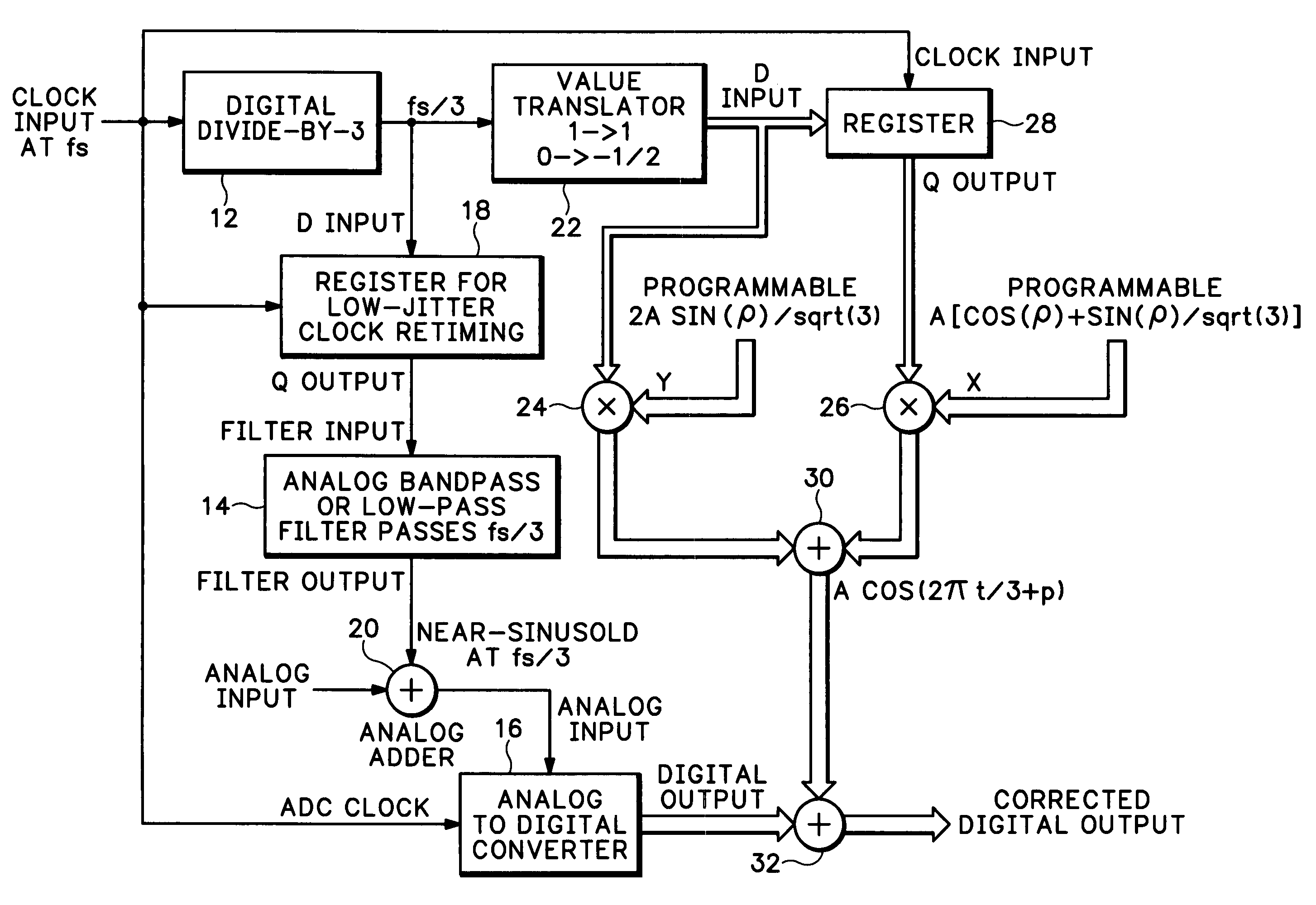
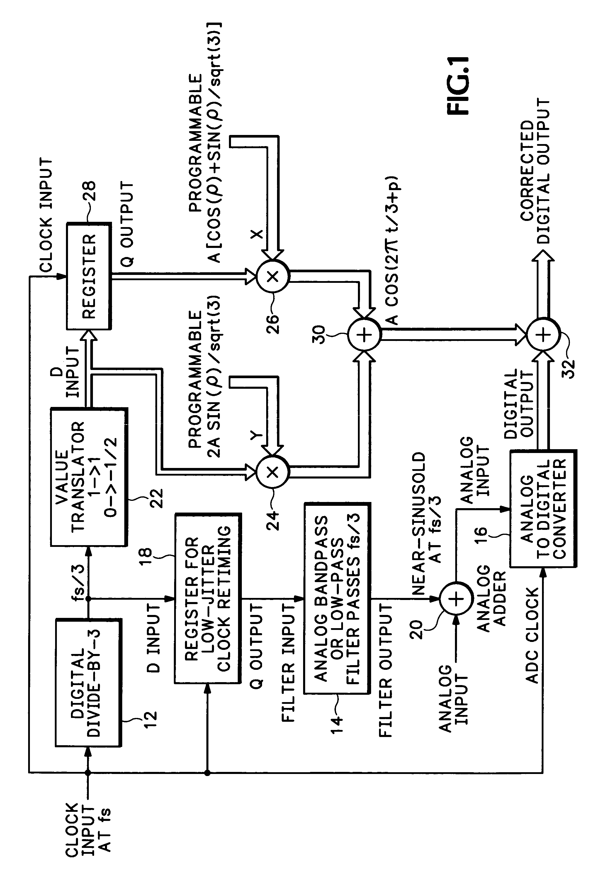
[0018]Referring now to FIG. 1, a clock signal having a sample frequency of fs is input to a divide-by-three circuit 12 to generate the following sequence:

W(t)=(1, 0, 0, 1, 0, 0, 1, 0, 0, 1, . . . )

or alternatively

W(t)=(1, 1, 0, 1, 1, 0, 1, 1, 0, 1, . . . )

or any other sequence having a repetition period of fs / 3 such that its harmonics are at (2fs / 3, 3fs / 3. 4fs / 3. 5fs / 3. 6fs / 3, . . . ). These frequencies alias to sampled frequencies (fs / 3, DC, fs / 3, fs / 3, DC, . . . ). A simple bandpass or lowpass analog filter 14 applied to the digital sequence removes DC and most of the harmonics prior to entry into a multi-stage ADC 16, although the filter performance is not critical as the non-DC harmonics all lie on fs / 3. More importantly the serial digital stream is re-clocked with a low-phase-noise, or low-jitter, register device 18, as noise on its output is being sampled by the ADC 16. The resulting output from the analog filter 14 is a near-sinusoid at fs / 3 which is input to an adder 20 to w...


PUM


Abstract

A dither system for a quantizing device, such as a multi-stage pipelined analog-to-digital converter (ADC), derives a dither signal from a clock signal having a sample frequency, the dither signal having a frequency that is one-third of the sample frequency. The dither signal is easily converted to analog and added at the input of the quantizing device to an analog signal to be digitized. A cancellation signal circuit generates a cosine-wave signal from a digital version of the dither signal and programmable coefficients that are a function of amplitude and phase. The cosine-wave signal is combined with the digital output signal from the quantizing device to produce a corrected digital output signal having reduced quantization distortion.

Description

BACKGROUND OF THE INVENTION[0001]The present invention relates generally to dither for quantizing devices, and more particularly to the correction of quantization errors in electonic devices or systems such as analog-to-digital converters (ADCs), and more specifically multi-stage ADCs.[0002]Fourier theory requires that:[0003]a) all repetitive signals of period T may be expressed as a sum of a DC offset, a fundamental sine wave of period T, and the harmonics of the fundamental;[0004]b) the fundamental and harmonics each have an amplitude and phase that is uniquely defined by the shape of the repetitive signal.A sine frequency is the reciprocal of its period or cycle time, so the fundamental frequency is 1 / T cycles per second or Hertz. A harmonic of a sine wave of period T is a frequency that is an integer multiple of the fundamental frequency so the nth harmonic has frequency n / T or a period of T / n.[0005]In mathematical terms a real signal Y(t) that repeats with frequency f may be ex...

Claims


Application Information

Patent Timeline
IPC IPC(8): H03M1/08H03M1/12H03M1/20H03M1/10H03M1/06
CPCH03M1/0639H03M1/12
Inventor SLAVIN, KEITH R.
Owner TEKTRONIX INC
Why Eureka
Try Eureka