Apparatus and method for re-outputting image data under different conditions depending on time passing from output of the image data

Inactive Publication Date: 2005-09-27
MINOLTA CO LTD
View PDF3 Cites 63 Cited by
  • Summary
  • Abstract
  • Description
  • Claims
  • Application Information

AI Technical Summary

Benefits of technology

[0022]According to the present invention, after certain image data is output, the image data can be output again without input of a password if an operator is kept detected. After output of the image data, if absence of the operator is detected once, input of a password is required for outputting the image data again. In other words, re-output of image data requires input of a password i

Problems solved by technology

However, this image forming apparatus requires input of a personal identification number each time image data is to be output, and thus has a problem of significantly poor operability especially when an image which was read at an immediately preceding time should be printed out repeatedly, for example, when an image is to be printed out after a trial printing.
These image for

Method used


Image

  • Apparatus and method for re-outputting image data under different conditions depending on time passing from output of the image data
  • Apparatus and method for re-outputting image data under different conditions depending on time passing from output of the image data
  • Apparatus and method for re-outputting image data under different conditions depending on time passing from output of the image data

Examples


first embodiment

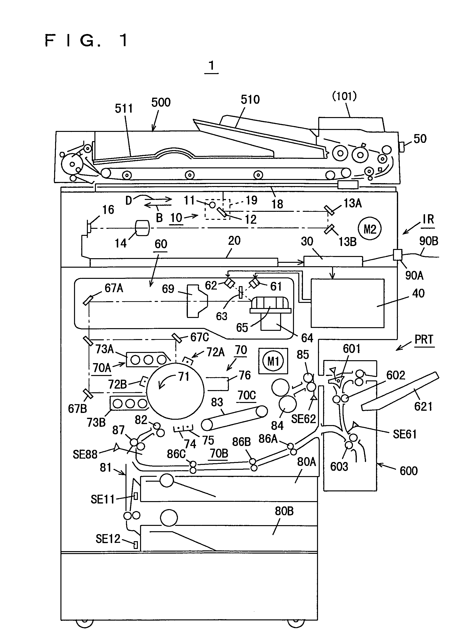
[0039]FIG. 1 is a cross section showing an entire structure of a copying machine 1 as one example of image forming apparatuses according to the present invention.

[0040]Referring to FIG. 1, copying machine 1 includes: a scan system 10 reading an original document and converting it into an image signal; an image signal processing unit 20 processing the image signal sent from scan system 10; an image memory unit 30 storing image data input from image signal processing unit 20; a print processing unit 40 driving semiconductor lasers 61 and 62 based on the image data input from image memory unit 30; an optical system 60 synthesizing two laser beams from respective semiconductor lasers 61 and 62 and directing the resultant beam onto a predetermined exposure position on a photoreceptor drum 71; and an image forming system 70 developing a latent image formed by exposure, and transferring and fixing it onto a sheet of paper to form an image. Copying machine 1 further includes: an operation p...

second embodiment

[0099]The second embodiment according to the present invention is hereinafter described. The second embodiment is different from the first embodiment in the process of memory recall control only, and only this difference is discussed below.

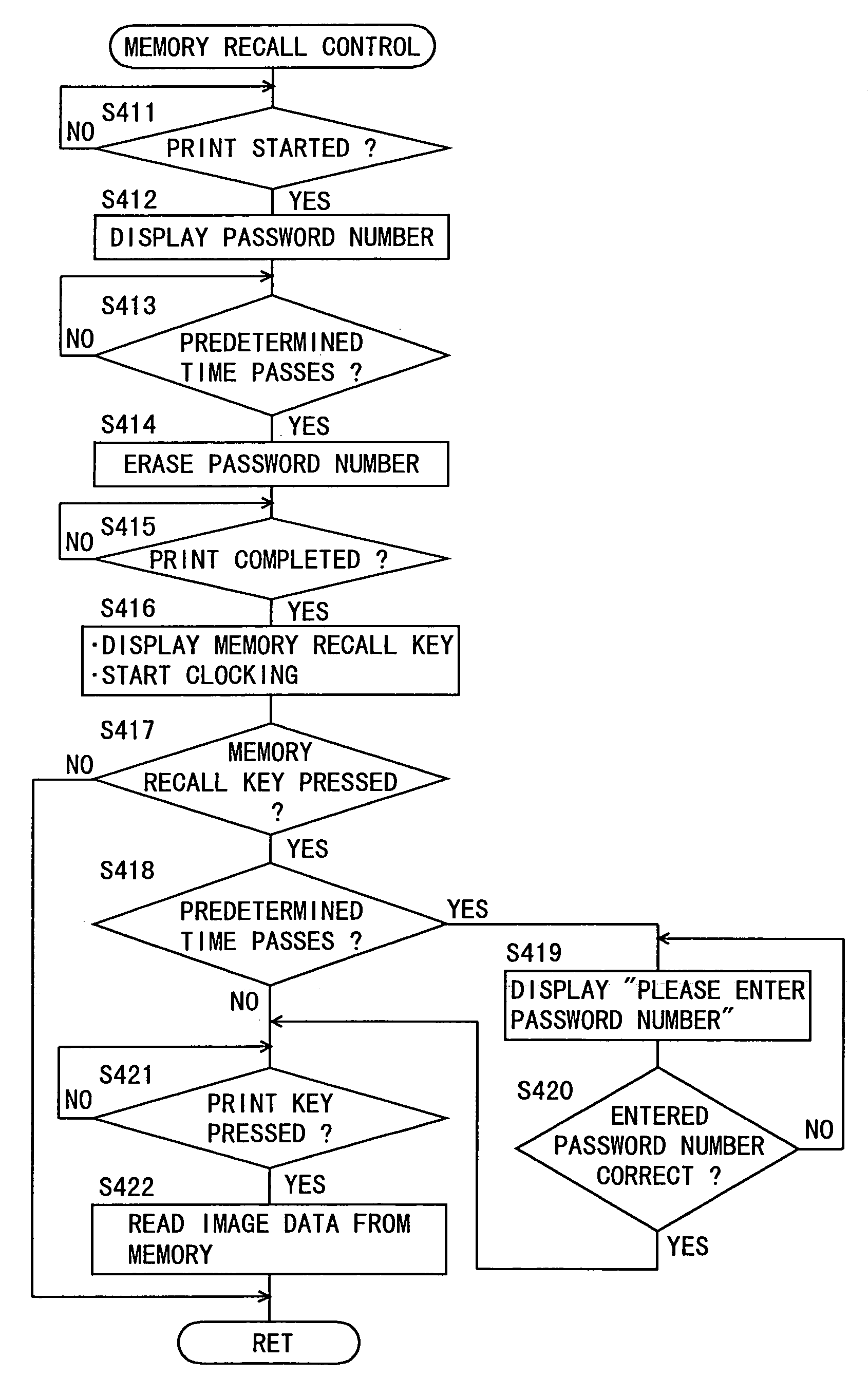
[0100]FIG. 10 is a flowchart showing a subroutine of the memory recall control process according the second embodiment.

[0101]Referring to FIG. 10, CPU 122 determines first in S431 whether printing operation is started or not. If CPU. 122 judges that the printing operation is started, it proceeds to S432. In S432, CPU 122 causes message display section 108 to display a password number corresponding to image data which is currently printed and then proceeds to S433. In S433, CPU 122 determines whether a predetermined time has passed from start of the printing operation in S431. This predetermined time may be equivalent to the predetermined time explained in conjunction with S413 (see FIG. 8). If CPU 122 judges that the predetermined time has passed,...


PUM


Abstract

When an image forming operation by a copying machine is completed, a memory recall key is displayed on a touch panel of an operation panel. If a user intends to output image data again, which has been stored in the copying machine and output once, the user presses the memory recall key. If the memory recall key is pressed before a predetermined time passes from the point of time when the image data to be output again is first output, that image data is directly output again. On the other hand, if the memory recall key is pressed after the predetermined time passes from the first output of the image data to be output again, that image data is output again on condition that a password number is entered.

Description

[0001]This application is based on application No. 11-295173 filed in Japan, the contents of which is hereby incorporated by reference.BACKGROUND OF THE INVENTION[0002]1. Field of the Invention[0003]The present invention relates to apparatuses and methods for outputting image data. In particular, the invention relates to an image data outputting apparatus and an image data outputting method for outputting image data again, which has once been output and stored in the apparatus, by a simple control method while ensuring confidentiality.[0004]2. Description of the Related Art[0005]Examples of the image data outputting apparatus include a printer which outputs image data taken in by a scanner and the like as an image, as well as a facsimile device which outputs taken image data directly to another device.[0006]There is also a printing system for multiple purposes as one of conventional image data outputting apparatuses. The conventional printing system stores image data in a memory suc...

Claims


Application Information

Patent Timeline
IPC IPC(8): B41J29/00B41J5/30G03G21/04G06K15/02G06F13/00G06F3/12H04L9/32H04N1/00B41J29/38H04N1/21H04N1/32H04N1/44
CPCH04N1/32486H04N2201/0091H04N2201/0098
Inventor YAMADA, TATSUTOSHITAKESADA, YOSHIKAZU
Owner MINOLTA CO LTD
Why Eureka
Try Eureka