Disk drive and disk drive control method

Inactive Publication Date: 2005-09-27
PANASONIC CORP
View PDF2 Cites 12 Cited by
  • Summary
  • Abstract
  • Description
  • Claims
  • Application Information

AI Technical Summary

Benefits of technology

[0009]The present invention has been made to solve the above-stated conventional disadvantages. It is, therefore, an object of the present invention to improve positioning accuracy for p

Problems solved by technology

However, the inherent mechanical resonance of an actuator of the head makes the positioning control system instable.
Under these circumstances, there is naturally a limit to setting the control frequency high.
However, the servo information on the disk is discrete information having a constant sampling cycle and the head position signal that reproduces the servo information is not a continuous signal.
Because of the restriction of the sampling frequency of the servo information, a control band of the disturbance estimation means has an upper limi

Method used


Image

  • Disk drive and disk drive control method
  • Disk drive and disk drive control method
  • Disk drive and disk drive control method

Examples


first embodiment

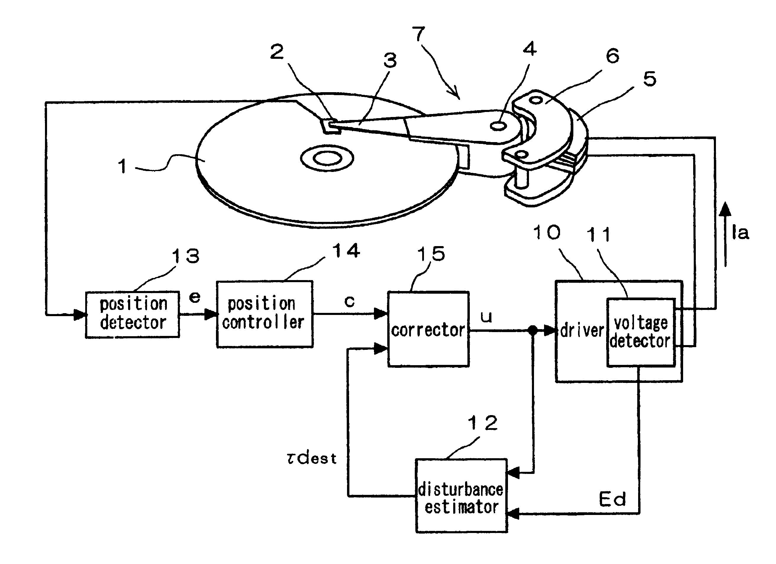
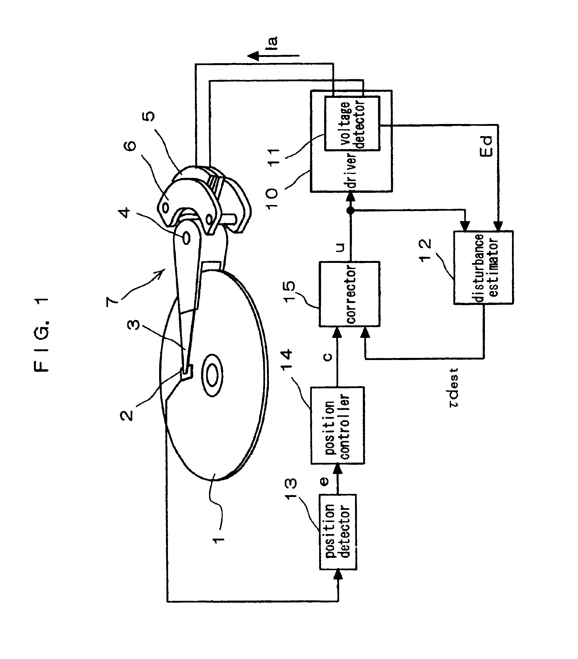
[0292]FIG. 1 is a block diagram illustrating the configuration of a disk drive in the first embodiment according to the present invention. In FIG. 1, reference numeral 1 indicates a magnetic disk (hereinafter, “disk”), which is rotated by a spindle motor (not shown). Reference numeral 2 indicates a magnetic head (hereinafter, “head”) which records and reproduces data on and from the disk 1, and 3 indicates an arm which rotates the head 2 mounted on one end of the arm 3 around a bearing 4 and thereby moves the head 2 to a target track on the disk 1. Reference numeral 5 indicates a driving coil provided in a rear end of the arm 3, and 6 indicates a stator (yoke) which surface opposite to the driving coil a magnet (permanent magnet, not shown) is arranged on. The stator 6 consists of a pair of yokes opposite each other through a cavity and the magnet is fixedly attached to at least one of the yokes in the cavity. A magnetic flux generated from the magnet arranged on the stator 6 and a ...

second embodiment

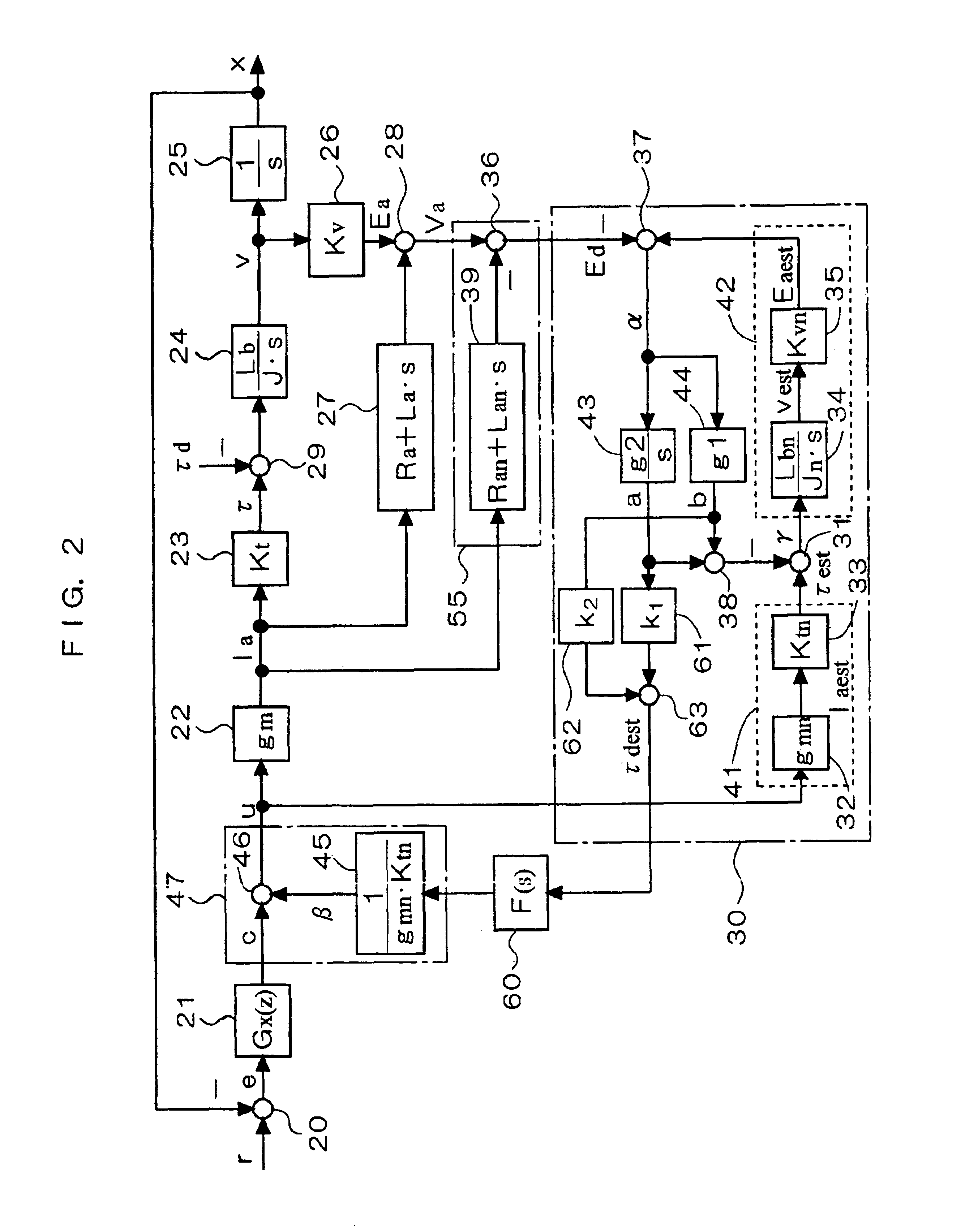
[0352]FIG. 9 is a block diagram illustrating the concrete configuration of the disturbance detector 12 that constitutes a disk drive in the second embodiment according to the present invention. Components having like functions as those in the block 30 shown in FIG. 2 which illustrates the configuration of the disk drive in the first embodiment are indicated by the same reference numbers and are not described herein repeatedly.

[0353]In the block 30 shown in FIG. 2, the proportional signal b is multiplied by k2 by the multiplier 62 and the multiplied signal is input to the adder 63. In FIG. 9, by contrast, the proportional signal b is input to the multiplier 62 through a high frequency cut-off filter 64 which has a transfer function of Fb(s).

[0354]FIGS. 10A and 10B are time response waveform views for describing the disturbance suppression effect of the disturbance estimator 12 of the disk drive in this embodiment while the coefficients k1 and k2 of the multipliers 61 and 62 shown in ...

third embodiment

[0362]FIG. 11 is a block diagram illustrating the configuration of a disk drive in the third embodiment according to the present invention. FIG. 12 is a block diagram illustrating the overall configuration of a head positioning control system in this embodiment. Components having like functions as those in the first embodiment are indicated by the same reference numerals and are not described herein in detail.

[0363]The third embodiment differs from the first embodiment shown in FIG. 1 in the signals input to a disturbance estimator 16. In the first embodiment, the voltage signal Ed generated by the voltage detector 11 and the driving signal u are input to the disturbance estimator 12. In the third embodiment, the voltage signal Ed generated by the voltage detector 11 and the position control signal c generated by the position controller 14 are input to the disturbance estimator 16. That is, the position control signal c is used in place of the driving signal u.

[0364]The disturbance ...


PUM


Abstract

A position detector generates a position error signal corresponding to a current position of a head, a position controller generates a position control signal from the position error signal, a voltage detector detects a voltage signal generated when driving an actuator by a driver, a disturbance estimator generates a disturbance estimation signal from a driving signal and the voltage signal, and a corrector outputs the driving signal from the disturbance estimation signal and the position control signal. The disturbance estimator includes a comparator which compares the disturbance estimation signal with a voltage signal and which outputs a deviation signal, and an adder which adds a signal obtained by multiplying an integral signal, which is obtained by integrating the deviation signal, by a first coefficient and a signal obtained by multiplying a proportional signal proportional to the deviation signal by a second coefficient, and which generates the disturbance estimation signal. The disturbance estimation signal suppresses a tracking deviation of the head due to a disturbance such as an inertial force applied to the head actuator and stabilizes head positioning control.

Description

BACKGROUND OF THE INVENTION[0001]1. Field of the Invention[0002]The present invention relates to a disk drive which highly accurately positions a recording / reproducing head on a target track of a disk serving as a recording medium by an actuator. More specifically, the present invention relates to a technique for suppressing deviation of a head from a target track by a disturbance that acts on an actuator.[0003]The present invention also relates to a disk drive having a load / unload mechanism which unloads a head to a head rest member such as a ramp block outside of a disk when the head is stopped and which loads the head onto a disk surface from the head rest member when the head is used, and to a technique for stably loading the head onto the disk surface under appropriate velocity control even if a disturbance on the head rest member is great.[0004]2. Description of the Related Art[0005]In recent years, disk drives such as magnetic disk drives are increasingly made small in size a...

Claims


Application Information

Patent Timeline
IPC IPC(8): G11B5/55G11B5/596
CPCG11B5/5526G11B5/59627
Inventor INAJI, TOSHIOKOHSO, HIROSHIMIYATA, KEIZO
Owner PANASONIC CORP
Why Eureka
Try Eureka