Paper cleaning buff

a technology for cleaning buffs and paper rolls, applied in carpet cleaners, instruments, photosensitive materials, etc., can solve the problems of ineffective cleaning effect of ordinary web cleaners using only vacuums to remove fibers and dust from paper rolls, difficulty in ensuring proper balance, and difficulty in maintenance people handling cleaning rolls, etc., to achieve easy resurfacing, less subject to vibration, and less subject to damage

Inactive Publication Date: 2005-10-04
KAIM WAYNE K
View PDF23 Cites 7 Cited by
  • Summary
  • Abstract
  • Description
  • Claims
  • Application Information

AI Technical Summary

Benefits of technology

[0008]It is a feature of the present invention to provide a paper cleaning apparatus with a buffing roll which may be easily resurfaced.
[0009]It is a further feature of the present invention to provide a paper cleaning apparatus with a buffing roll which is less subject to damage.
[0010]It is another feature of the present invention to provide a paper cleaning apparatus with a buffing roll which is less subject to vibration.
[0011]It is yet another feature of the present invention to provide a paper cleaning apparatus with a buffing roll which is intrinsically stiffer.

Problems solved by technology

An ordinary web cleaner using only vacuum to remove fibers and dust from a paper begins to be ineffectual as paper speeds increase above 800 feet per minute (13 fps) because the boundary layer of air which moves with the paper web becomes more difficult to penetrate.
The buffing rolls are operated at relatively high speeds and, because of space limitations and overall cost, are relatively narrow in diameter—typically between three-and-one-half inches and four-and-one-half-inches in diameter.
The construction of the prior art buffing rolls which employ a solid central steel core overlain with disks of cloth results in some difficulty in assuring proper balance so that the cleaning rolls do not vibrate.
If the central core is made too large in diameter, it can be difficult for maintenance people to handle the cleaning rolls.
Further, renewing the soft outer surface of the rolls requires returning the rolls to the factory with the added cost of shipping to and from the factory.

Method used


Image

  • Paper cleaning buff
  • Paper cleaning buff
  • Paper cleaning buff

Examples


Embodiment Construction

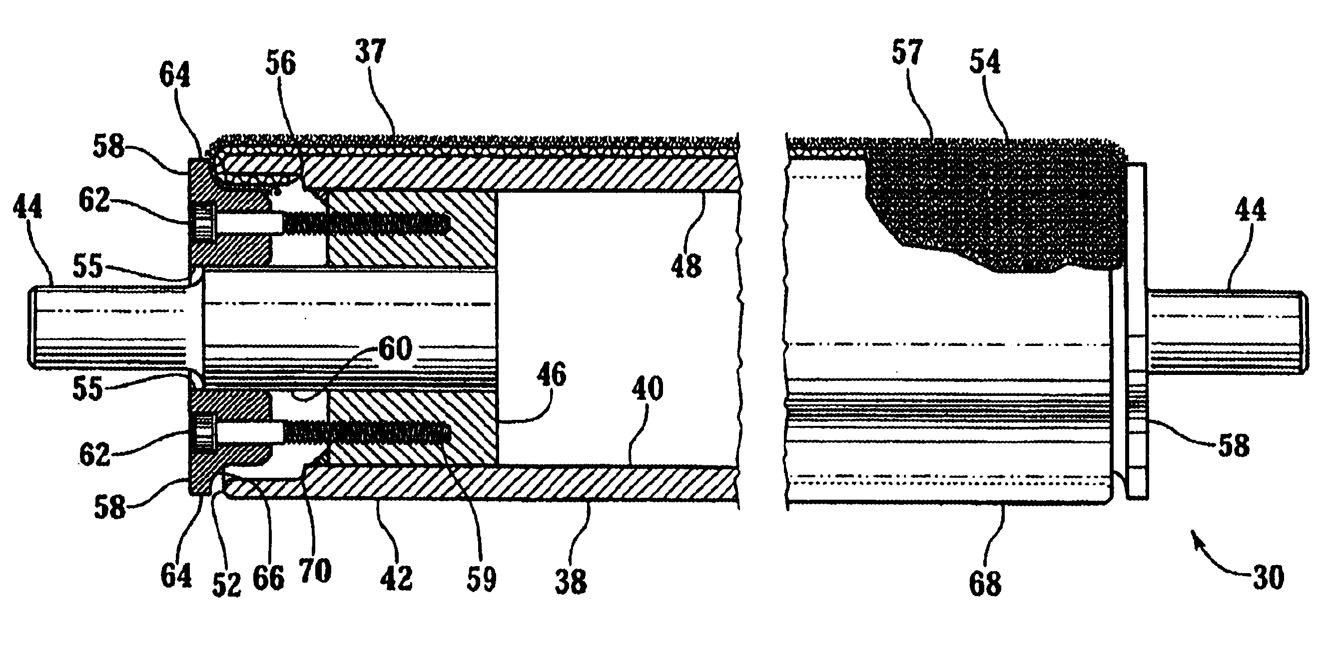
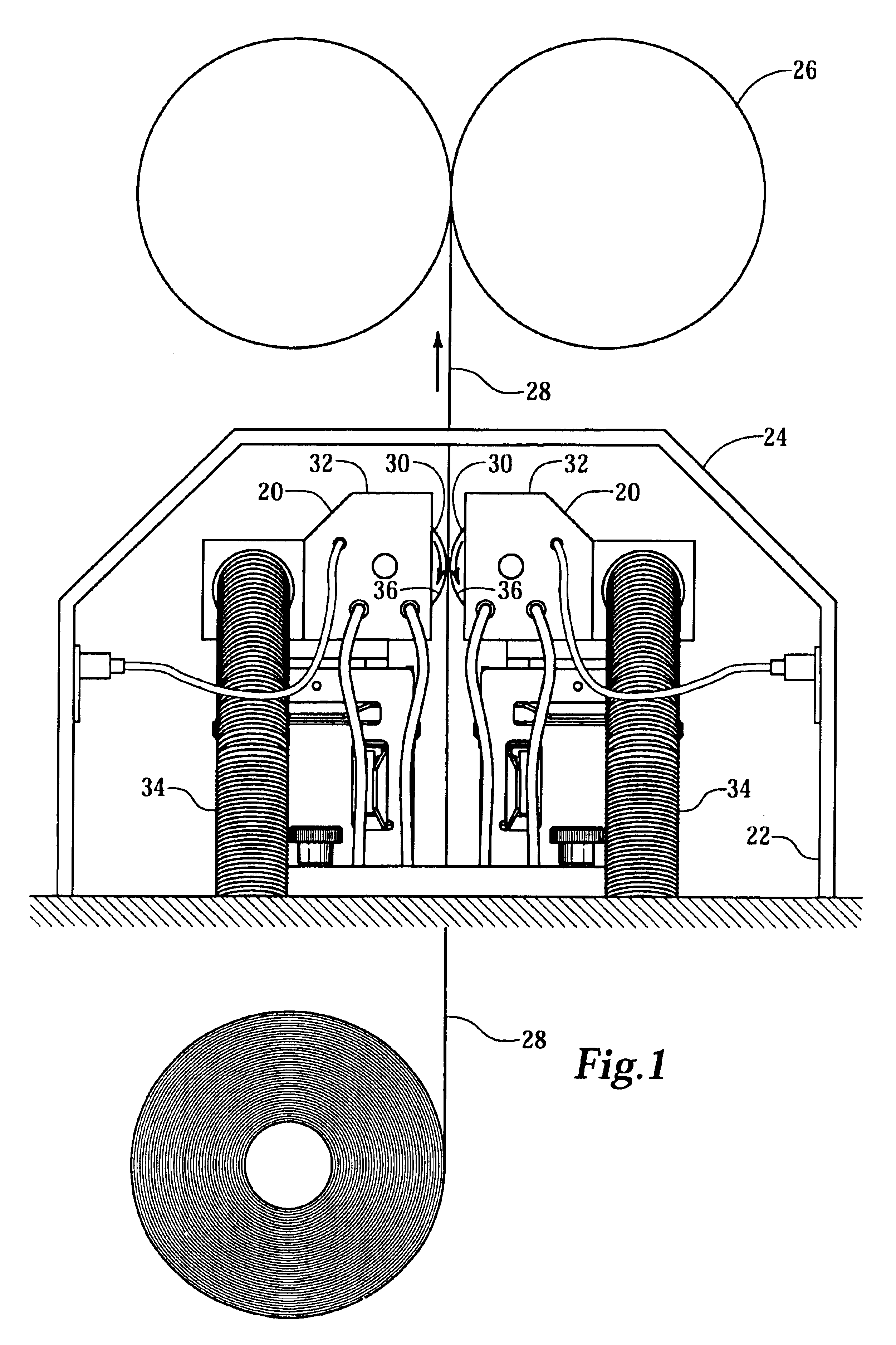
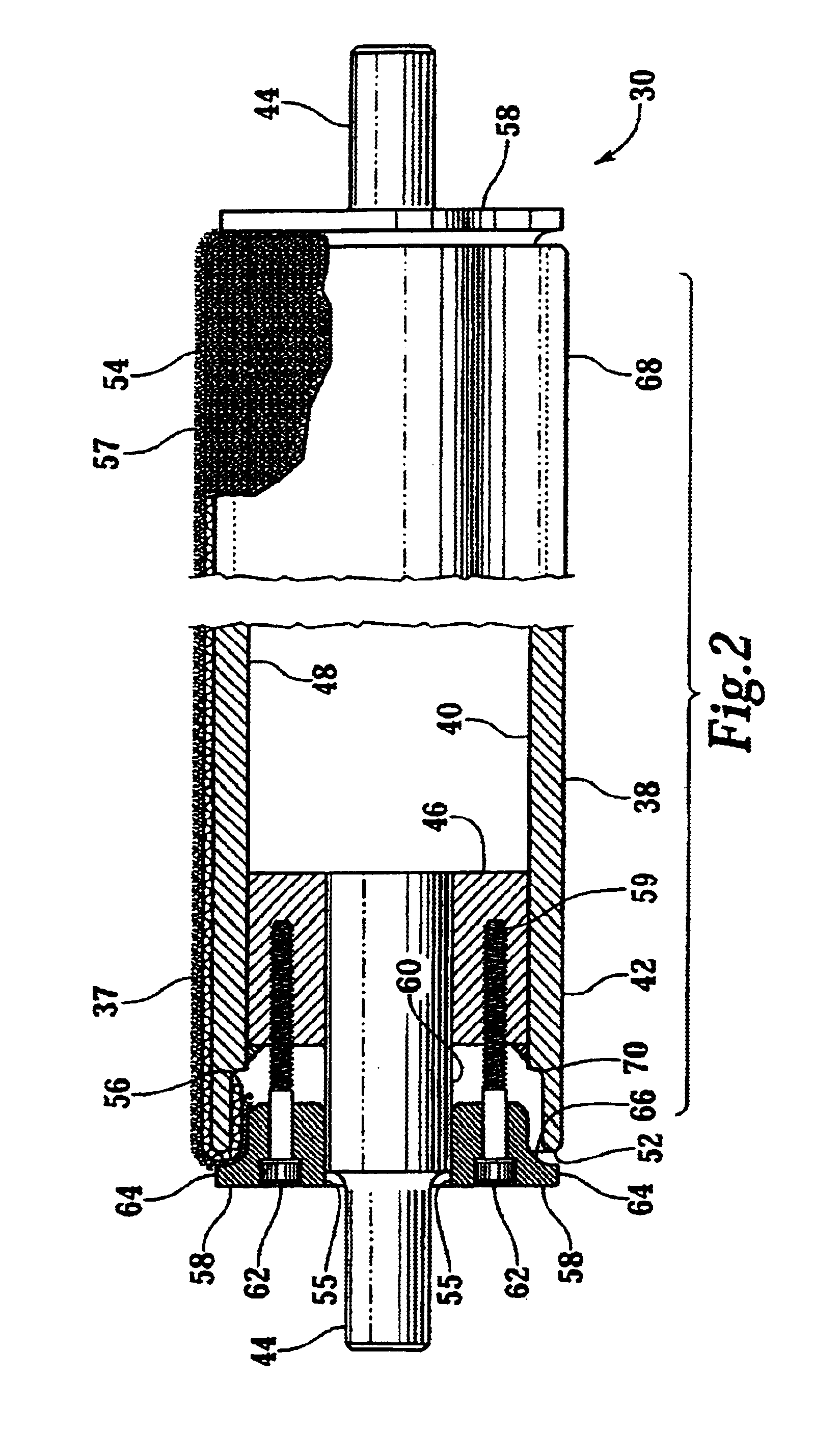
[0015]Referring more particularly to FIGS. 1-2, wherein like numbers refer to similar parts, a pair of buffing machines 20 are shown in FIG. 1, positioned within an archway 22 formed by a frame 24 of a printing press 26. A paper web 28 passes between opposed buffing rolls 30 which are mounted within vacuum hoods 32 which are connected to vacuum hoses 34. The buffing rolls 30 are rotated while air is drawn through the hoods 32. The rolls are rotated towards each other (one in the clockwise direction and one in the counter clockwise direction) in operation. As shown in FIG. 2, the buffing rolls 30 have a soft surface 36 composed of a profusion of radially extending wool fibers 37 which present a hairy surface. The fibers 37 and the air currents create or interact with the boundary layer of air moving with the paper web 28, causing lose paper fibers and dust containing various components such as clay, starch or fiber particles to becoming entrained in the boundary layer attached to the...


PUM


Abstract

A paper cleaning apparatus employs a paper buffing roll which has a lightweight hollow cylindrical core mounted between stub shafts. The stub shafts are mounted to bearings and the hollow core is arranged to be driven at approximately 3,450 to approximately 4,450 RPM. The surface of the cylindrical core is given a rough surface over which a wool cloth jacket is placed. The cloth sleeve is clamped in place by retaining end caps which fit over the stub shafts and clamp the sleeve against the ends of the hollow cylindrical core. The cloth sleeve is shrunk onto the surface of the cylindrical core with hot water or steam. The cloth sleeve is frayed to form a soft outer surface, with radially extending fibers.

Description

CROSS REFERENCES TO RELATED APPLICATIONS[0001]Not applicable.STATEMENT AS TO RIGHTS TO INVENTIONS MADE UNDER FEDERALLY SPONSORED RESEARCH AND DEVELOPMENT[0002]Not applicable.BACKGROUND OF THE INVENTION[0003]The present application relates to apparatus for cleaning a moving paper web in general and particularly to cleaners which affect the boundary layer of air moving with the paper web.[0004]In a typical web offset press an image to be printed is transferred to a rubber blanket which is brought into contact with a moving web of paper onto which the image is printed. Minute amounts of loose fiber and dust from the paper web stick to the rubber blankets so that over time the blankets become dirty and must be cleaned to maintain image quality. It has been found that the frequency with which the rubber printing blankets must be cleaned can be substantially decreased if the paper web is precleaned before it is printed upon. In my earlier patent, U.S. Pat. No. 6,178,589, which is incorpor...

Claims


Application Information

Patent Timeline
Patent Type & Authority Patents(United States)
IPC IPC(8): B08B1/04B08B1/02B08B5/04B08B5/00B41F23/00B08B5/02
CPCB08B1/02B08B1/04B08B5/026B08B5/04B08B5/043B41F23/002A46B2200/3093
Inventor KAIM, WAYNE K.
Owner KAIM WAYNE K
Why Eureka
Try Eureka