Endoscope Tip Part and Endoscope

Active Publication Date: 2014-03-20
OLYMPUS CORP
View PDF4 Cites 22 Cited by
  • Summary
  • Abstract
  • Description
  • Claims
  • Application Information

AI Technical Summary

Benefits of technology

[0044]Advantageous effects of the thus-configured endoscope tip part 1 and endoscope 2 of this embodiment will be described below.
[0045]With the endoscope tip part 1 of this embodiment, because the plastic first lens 5 of the illumination optical system 9 is integrated with the plastic tip part main body 4 through two-color molding, there is an advantage that the endoscope tip part 1 is less subject to damage even when an external impact is received, thus making it possible to improve impact resistance. Specifically, when the plastic first lens 5 is applied to a thin endoscope 2, even though the plastic first lens 5 is disposed at a short distance from a side surface that receives an impact, the plastic first lens 5 is less subject to damage due to the elasticity of the first lens 5 itself.
[0046]Furthermore, because the endoscope tip part 1 of this embodiment is formed through two-color molding, there is an advantage that cumbersome assembly work is not required, the number of parts can be reduced, and the manufacturing cost and the product cost can be reduced, unlike a conventional method of securing the illumination optical system 9 to a metallic tip part main body with an ad

Problems solved by technology

Furthermore, a first lens of the objective optical system and a first lens of the illumination optical system are disposed on the tip surface of the insertion section of the endoscope, and these first lenses may break or chip due to an impact

Method used


Image

  • Endoscope Tip Part and Endoscope
  • Endoscope Tip Part and Endoscope
  • Endoscope Tip Part and Endoscope

Examples


example 1

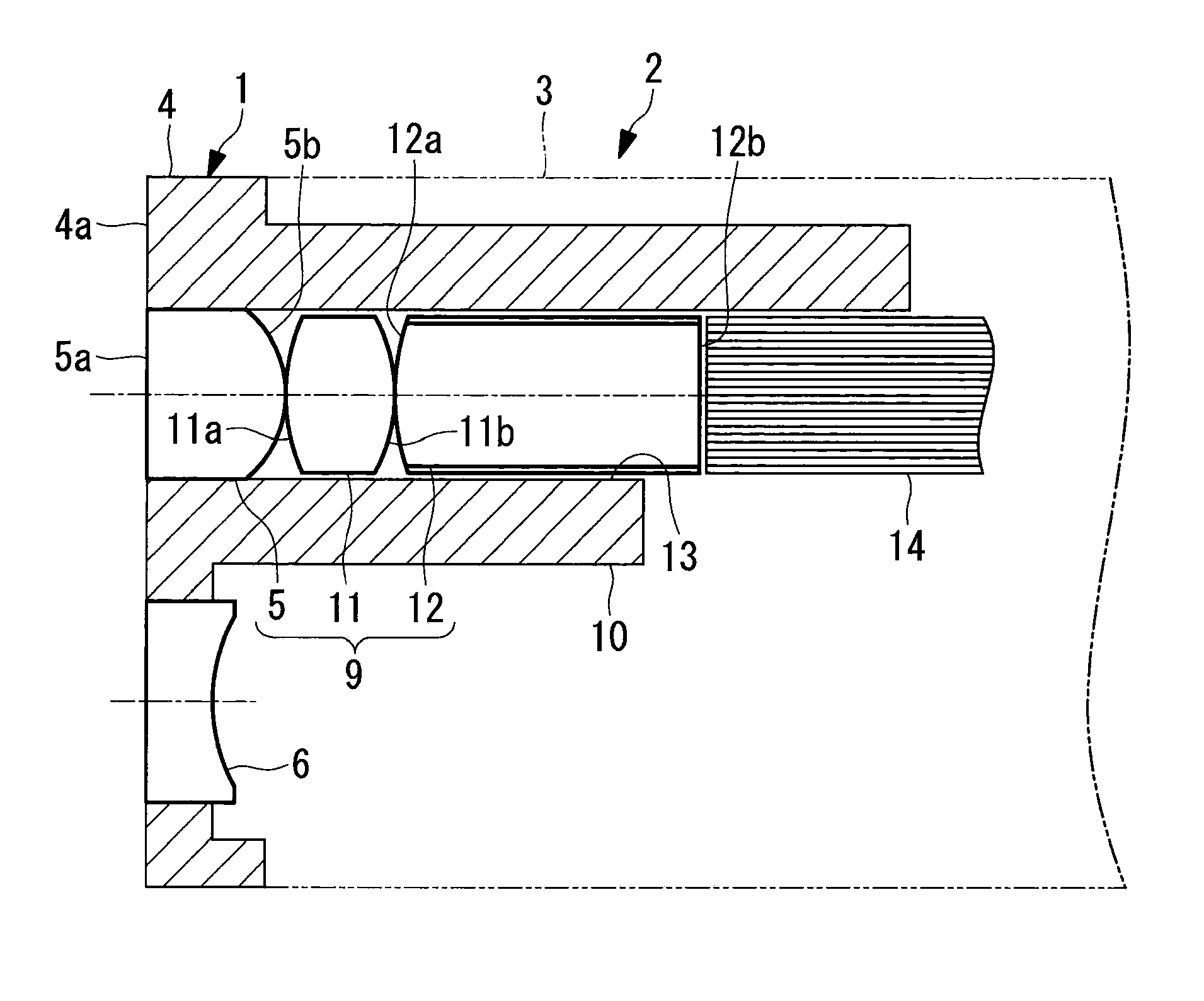
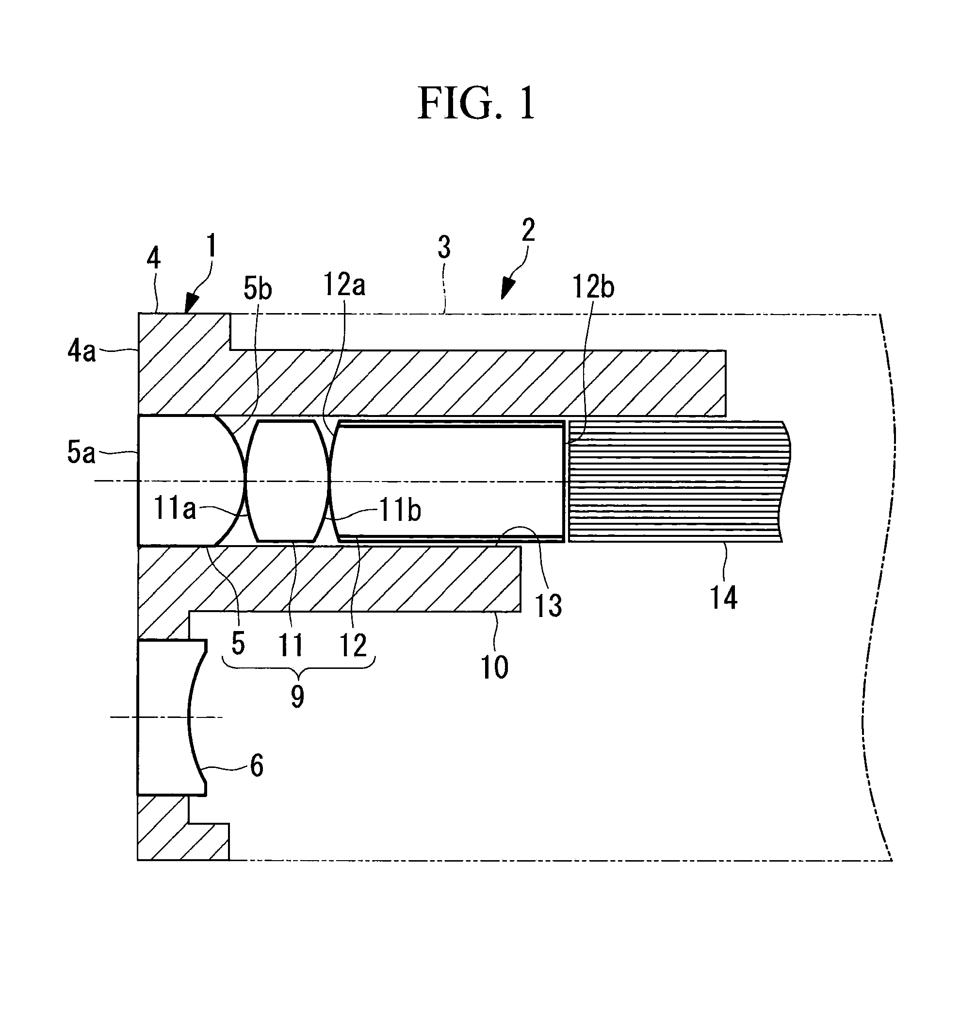
[0084]FIG. 5 shows the configuration of an illumination optical system 9 of the endoscope 2 according to this example, and Table 1 shows values of design data. The illumination optical system 9 is formed of, in order from the object side, the first lens 5 having positive refractive power, the second lens 11 having positive refractive power, and the third lens 12 having positive refractive index.

[0085]Note that the third lens 12 is a rod lens, and the surface thereof closer to the light source is an end surface to which light is emitted from the light guide fibers 14. The first lens 5 is integrated with the tip part main body 4 through two-color molding. Furthermore, the rear second lens 11 and third lens 12 are assembled by being butted against each other at the centers of the optical axes of the lenses.

[0086]Thus, the distance between the lens surfaces is 0. With this lens assembly method, spacing members for the lenses 5, 11, and 12 are not required, which achieves a reduction in ...

example 2

[0088]Table 2 shows values of design data of an illumination optical system 9 of the endoscope 2 according to this example. This illumination optical system 9 has the same configuration as that of Example 1 and is equivalent in terms of the assembly method, performance, and advantageous effects.

TABLE 2radius ofAbbelenssurfacecurvatureintersurfacerefractivenumberouternumberrdistance dindex Neνddiameter1∞1.651.6414723.2φ2.22−1.4503 2.381.541.8881540.76φ2.24−2.38053.68(rod)3.881.6522225.42φ2.26∞0refractive index of rod cladding: 1.514focal length: 1.00 mm

example 3

[0089]Table 3 shows values of design data of an illumination optical system 9 of the endoscope 2 according to this example. This illumination optical system 9 has the same configuration as that of Example 1 or Example 2 and is equivalent in terms of the assembly method, performance, and advantageous effects.

TABLE 3radius ofAbbelenssurfacecurvatureintersurfacerefractivenumberouternumberrdistance dindex Neνddiameter1∞1.61.6414723.2φ22−1.4303 2.781.551.8881540.76φ24−2.05053.37(rod)3.81.6522225.42φ26∞0refractive index of rod cladding: 1.514focal length: 1.00 mm

[0090]Table 4 shows values of conditional expressions (1) to (8) in the configurations of the respective examples.

TABLE 4conditionalexpressionExample 1Example 2Example 3(1)1.641.641.64(2)7.337.086.95(3)1.541.451.40(4)0.790.790.68(5)0.640.640.64(6)3.843.603.37(7)5.895.535.17(8)1.071.121.14

Additional Items

[0091]Note that, in the present invention, the following configurations can also be adopted.

Additional Item 1

[0092]An endoscope t...


PUM


Abstract

An endoscope tip part has impact resistance even when applied to a thin endoscope, and the light distribution characteristics thereof can be improved even at a wide angle of view. An endoscope tip part includes a tip part main body that is attached to the tip of an insertion section of an endoscope and a positive-power transparent-plastic tip lens that is integrated with the tip part main body through two-color molding. The tip lens is a lens that is located closest to an object, among optical elements constituting an illumination optical system of the endoscope, and the tip part main body is provided with an insertion hole into which two positive-power rear lenses that will be disposed behind the tip lens are inserted.

Description

CROSS-REFERENCE TO RELATED APPLICATIONS[0001]This is a continuation of International Application PCT / JP2012 / 081886, with an international filing date of Dec. 10, 2012, which is hereby incorporated by reference herein in its entirety. This application is based on Japanese Patent Application No. 2012-005293, the contents of which are incorporated herein by reference.TECHNICAL FIELD[0002]The present invention relates to an endoscope tip part and an endoscope.BACKGROUND ART[0003]In general, an objective optical system for acquiring images of an observation object and an illumination optical system for irradiating the observation object are arranged at the tip portion of an insertion section of an endoscope. Furthermore, an imaging device that acquires images of the observation object imaged by the objective optical system is installed in the insertion section.[0004]Furthermore, a first lens of the objective optical system and a first lens of the illumination optical system are disposed ...

Claims


Application Information

Patent Timeline
IPC IPC(8): A61B1/00A61B1/06
CPCA61B1/00096A61B1/00188A61B1/06A61B1/07G02B23/2469A61B1/00163
Inventor TAKATO, HIDEYASUKAMO, YUJITSUJI, YOSHIFUMI
Owner OLYMPUS CORP
Why Eureka
Try Eureka