
Method and apparatus for determining speed and properties of flowing fluids using NMR measurements

a technology of fluid speed and properties, applied in the direction of instruments, nmr measurement, borehole/well accessories, etc., can solve the problems of inability to accurately determine the actual properties of the reservoir fluid, measurement laboratory data may not be useful or relevant to the reservoir fluid properties, and laboratory results can still be tainted

Active Publication Date: 2005-10-04
SCHLUMBERGER TECH CORP
View PDF15 Cites 42 Cited by
  • Summary
  • Abstract
  • Description
  • Claims
  • Application Information

AI Technical Summary

Benefits of technology

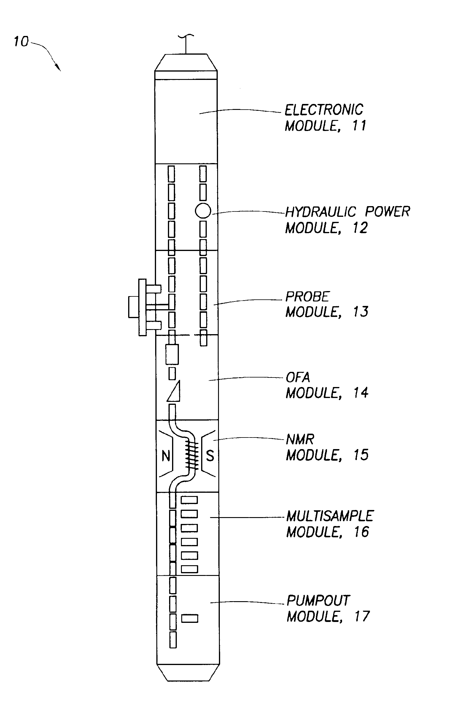
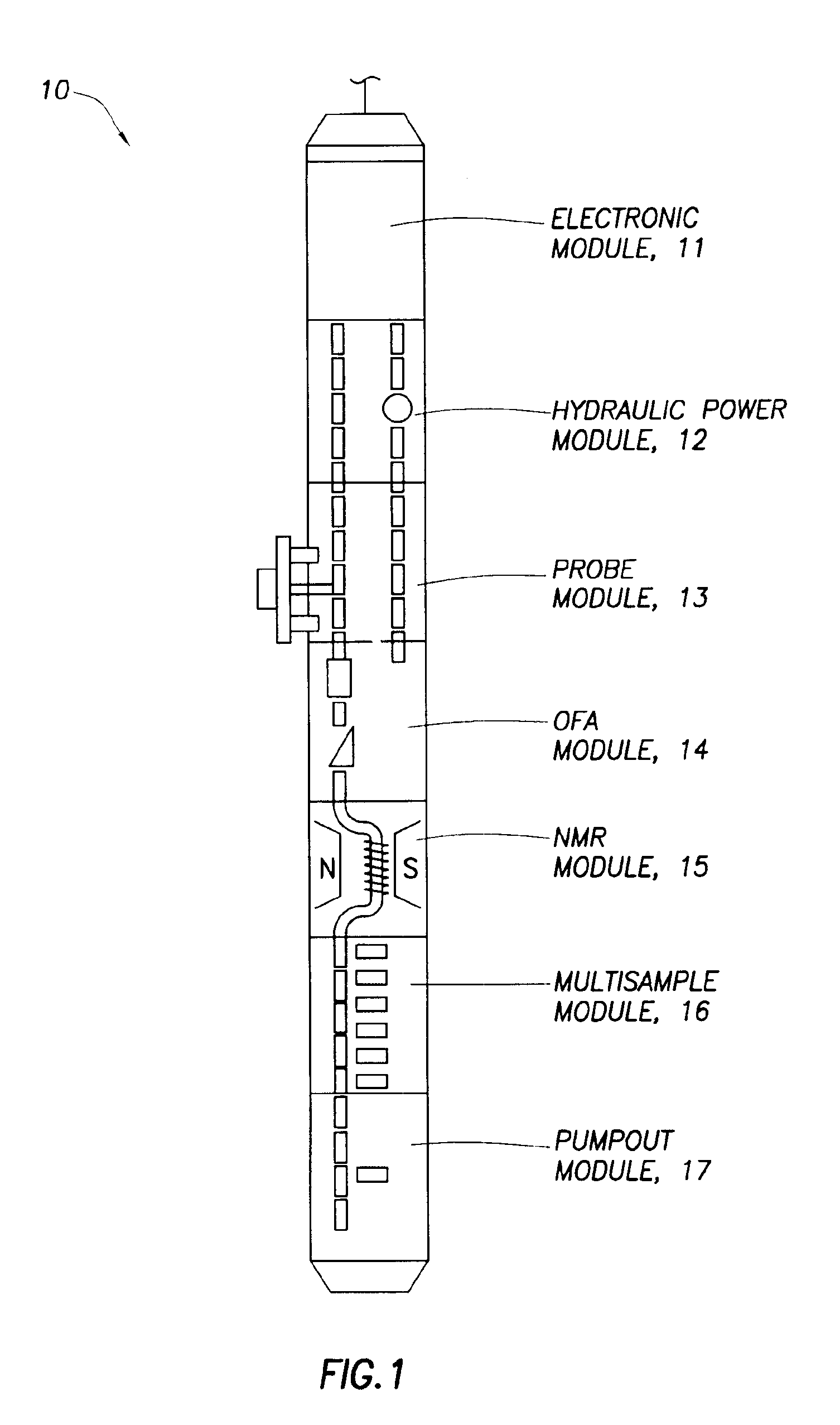
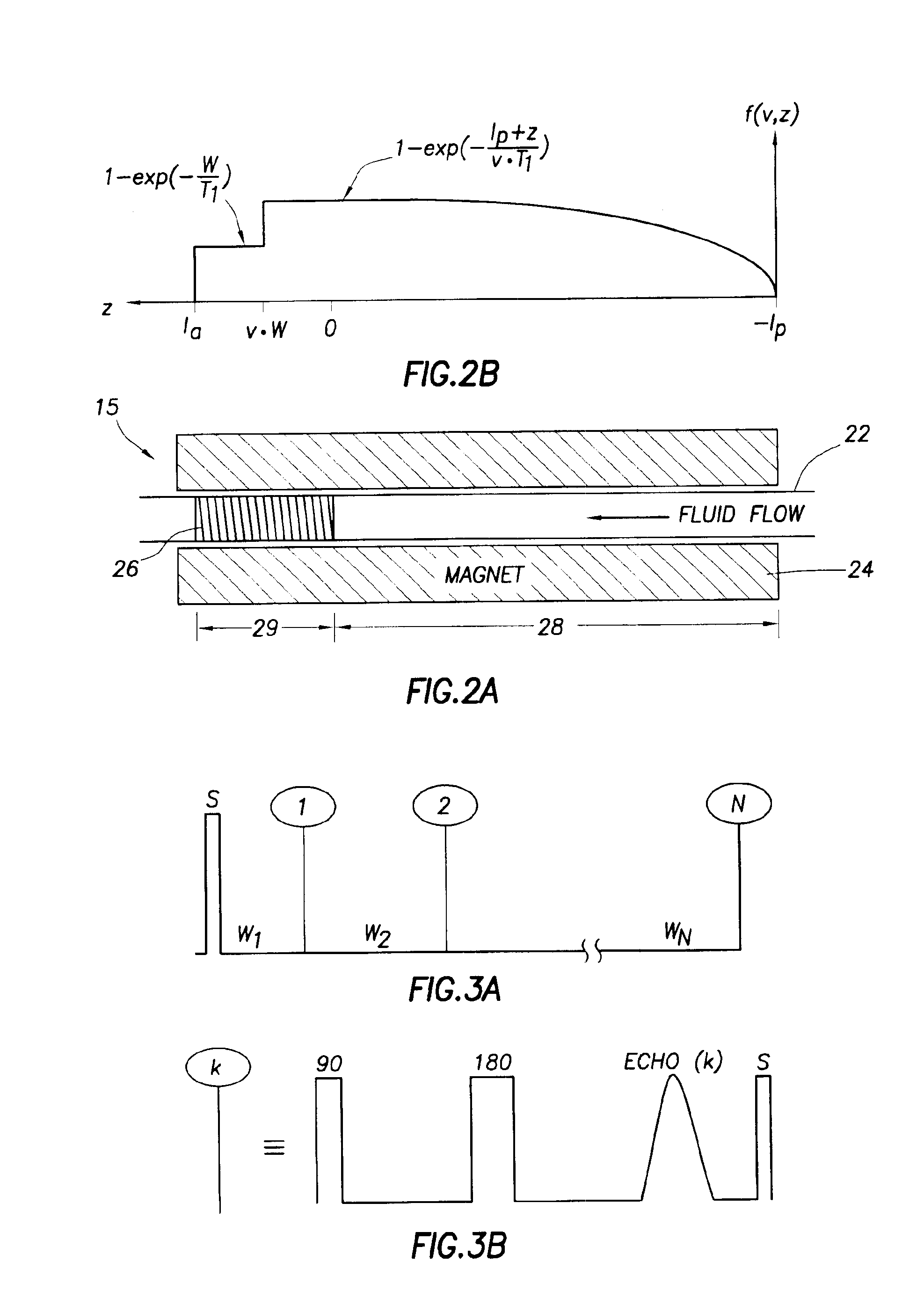
The patent text describes methods and apparatus for using nuclear magnetic resonance to determine properties of a flowing fluid and to monitor contamination in the fluid. The technical effects of the invention include improved accuracy in measuring flow speed and longitudinal relaxation times, as well as the ability to detect and measure contamination in the fluid. The apparatus includes a flow pipe with a prepolarization section and an investigation section, a magnet for creating a static magnetic field, and an antenna for generating an oscillating magnetic field and receiving the nuclear magnetic resonance signal.

Problems solved by technology

However, the laboratory data may not be useful or relevant to the reservoir fluid properties because the samples may be contaminated by mud filtrate.
In either case the contamination may render the measured laboratory data irrelevant to the actual properties of the in situ reservoir fluids.
In those cases where the samples brought to the surface have low or negligible contamination, laboratory results can still be tainted (e.g., by precipitation of solids caused by temperature changes).
However, none of these prior art patents disclose methods for determining flow speed or T1 of flowing fluids.
However, the FID signal is difficult to measure using permanent magnets because static magnetic field variations will result in signals that decay too fast for reliable detection.
Moreover, the King and Santos methods for determining flow speed do not account for the fact that there is a distribution of flow speeds in a pipe.
However, the computation requires prior knowledge of the fluid T1 distributions.

Method used


Image

  • Method and apparatus for determining speed and properties of flowing fluids using NMR measurements
  • Method and apparatus for determining speed and properties of flowing fluids using NMR measurements
  • Method and apparatus for determining speed and properties of flowing fluids using NMR measurements

Examples


Embodiment Construction

[0029]Embodiments of the invention relate to methods and apparatus for determining speeds and properties of flowing fluids using NMR measurements. The methods disclosed herein for determining flow speed do not depend on static magnetic field gradients.

[0030]Some embodiments of the invention also relate to methods for measuring longitudinal relaxation time (T1) of the fluid. The measurement of T1 provides a means for monitoring contamination levels in the reservoir fluids that are being withdrawn from the reservoir into a borehole fluid testing / sampling tool, such as the Modular Dynamics Tester tool sold under the trade name of MDT™ by Schlumberger Technology Corporation (Houston, Tex.) or any similar fluid sampling tool. Monitoring changes in T1 with time is useful for determining when to divert or stop the flow in order to: (1) to make in situ NMR measurements of longitudinal (T1) or transverse relaxation times (T2), diffusion coefficients (D), or chemical shift spectra, or (2) col...


PUM


Abstract

A method for determining a property of a flowing fluid by nuclear magnetic resonance includes applying a static magnetic field to the flowing fluid; acquiring a suite of nuclear magnetic resonance measurements on the flowing fluid using a pulse sequence comprising a spoiling pulse, a wait time, and an acquisition pulse sequence, wherein the suite of nuclear magnetic measurements have different values for the wait time; and fitting the suite of nuclear magnetic resonance measurements to a forward model for responses of the flowing fluid to derive a parameter selected from a flow speed, longitudinal relaxation times of the flowing fluid, and a combination thereof.

Description

BACKGROUND OF INVENTION[0001]1. Field of the Invention[0002]The invention relates generally to fluid characterization using nuclear magnetic resonance (NMR) instruments.[0003]2. Background Art[0004]The oil and gas industry has developed various tools capable of determining and predicting earth formation properties. Among different types of tools, nuclear magnetic resonance (NMR) instruments have proven to be invaluable. NMR instruments can be used to determine formation properties, such as the fractional volume of pore space and the fractional volume of mobile fluid filling the pore space. A general background of NMR well logging is described in U.S. Pat. No. 6,140,817.[0005]Nuclear magnetic resonance is a phenomenon occurring in a selected group of nuclei having magnetic nuclear moments, i.e., non-zero spin quantum numbers. When these nuclei are placed in a magnetic field (Bo, “Zeeman field”), they each precess around the axis of the Bo field with a specific frequency, the Larmor f...

Claims


Application Information

Patent Timeline
Patent Type & Authority Patents(United States)
IPC IPC(8): E21B49/08E21B49/00G01P5/08G01P5/00G01R33/44E21B47/13G01F1/716
CPCE21B49/08G01F1/716G01N24/081G01P5/08E21B2049/085E21B49/0875G01R33/54G01R33/563G01V3/32
Inventor FREEDMAN, ROBERT
Owner SCHLUMBERGER TECH CORP
Learn More