
System and method for concurrently addressing multiple radio frequency identification tags from a single reader

a radio frequency identification and reader technology, applied in the field of simultaneous addressing multiple rfid tags from a single reader, can solve the problems of slow multiple tag reading rate, large tag population, and need for complex timing circuits, so as to increase the range and throughput of the system and reduce the cost of the tag

Inactive Publication Date: 2005-10-04
RUIZHANG TECH LTD CO
View PDF9 Cites 100 Cited by
  • Summary
  • Abstract
  • Description
  • Claims
  • Application Information

AI Technical Summary

Benefits of technology

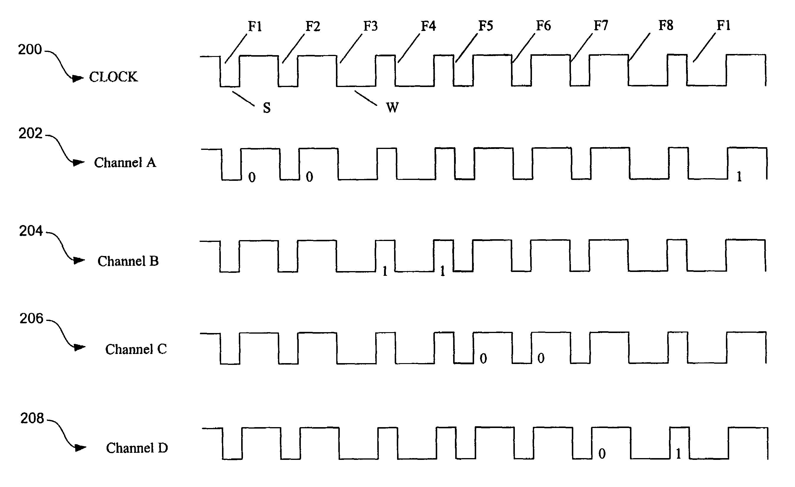
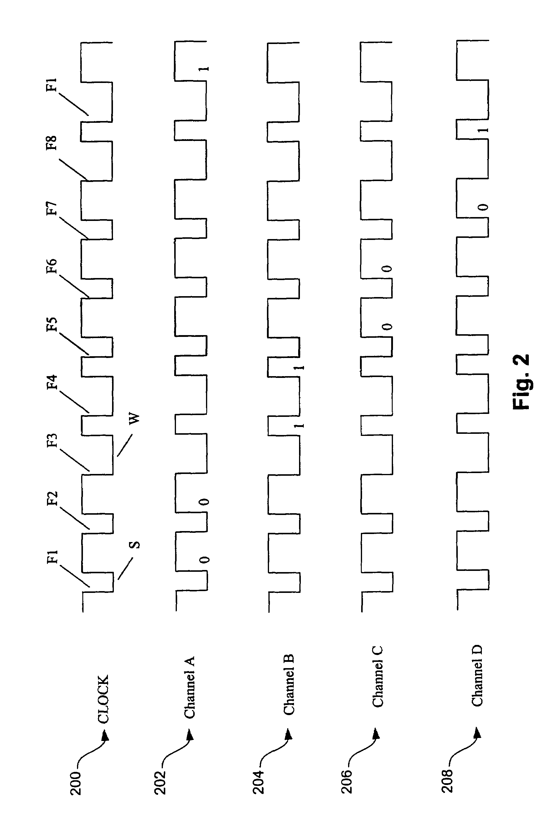
[0012]A system and method are provided in which each reader may conduct concurrent, yet independent, dialog with multiple tags at the same time using two or more phase channels. This increases the range and throughput of the system while decreasing the cost of the tag.
[0014]Upon receipt from the reader of an instruction for the tags to randomize, the tags randomly choose and assign a phase channel that will be their time reference for subsequent operation. Alternatively, the channel can be assigned by the reader. In either case, the phase channel assignment can be stored, preferably for at least one second, so that short-duration intermittent power losses do not alter the selected channel assignments.

Problems solved by technology

Existing anti-collision methods generally suffer from slow multiple tag reading rates, and read rates can be severely reduced with large tag populations.
If the clock frequency is too low for the desired data rates, “one shots” and complex timing circuits are required to control the ordering of events within the tag.
One problem inherent in the prior art is power constraint.
Also, as the input voltage decreases, propagation delays within the tag circuitry increases, thereby reducing the operational speed of the tag.
In many cases, the reduction in speed will cause the tag to operate improperly or not at all.
Another problem arises in a typical store that might have several readers and several overlapping areas of interrogation.

Method used


Image

  • System and method for concurrently addressing multiple radio frequency identification tags from a single reader
  • System and method for concurrently addressing multiple radio frequency identification tags from a single reader
  • System and method for concurrently addressing multiple radio frequency identification tags from a single reader

Examples


Embodiment Construction

[0027]The following description is the best embodiment presently contemplated for carrying out the present invention. This description is made for the purpose of illustrating the general principles of the present invention and is not meant to limit the inventive concepts claimed herein.

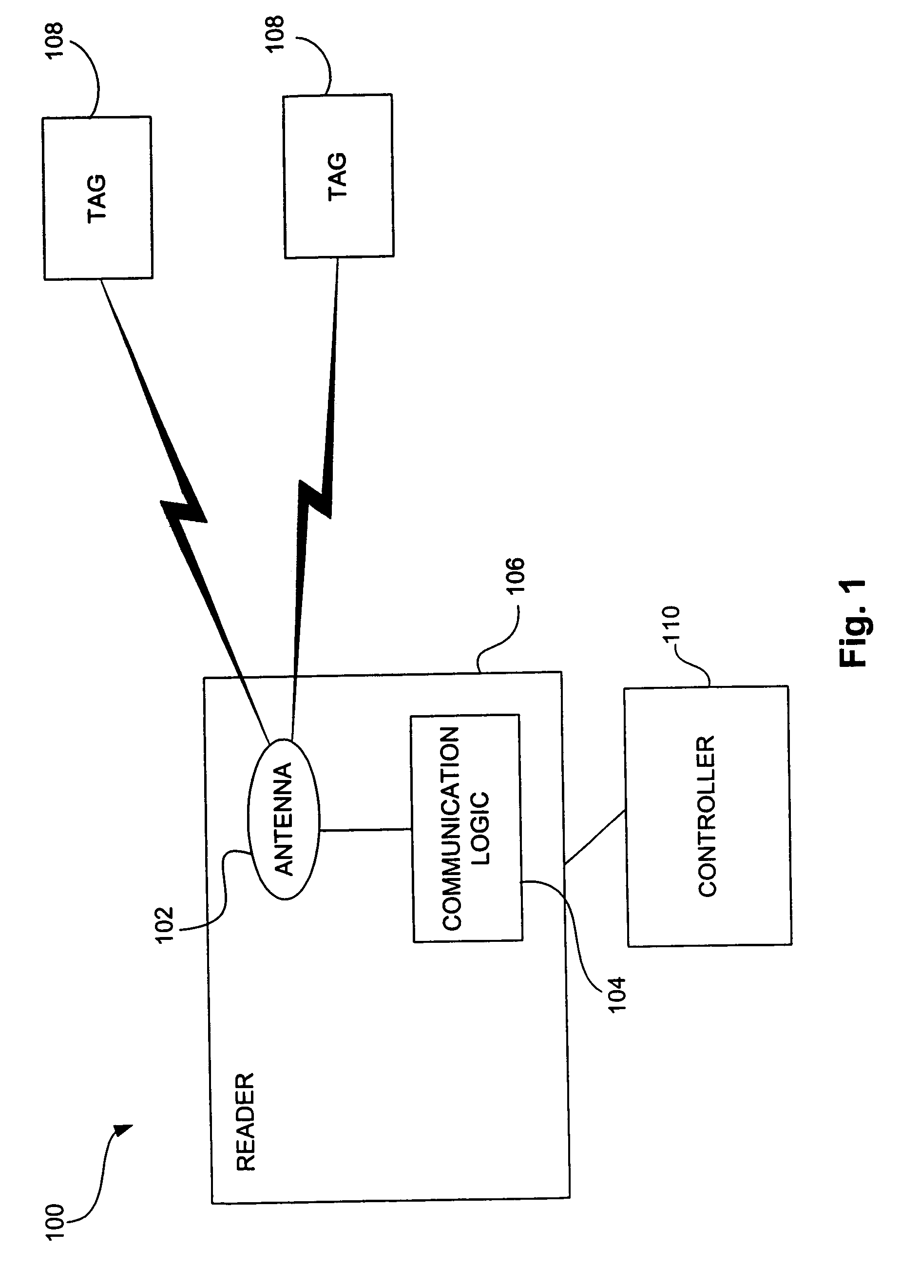
[0028]FIG. 1 depicts an RFID system 100 according to one embodiment. As shown, the system includes three components: an antenna 102 and transceiver 104 (here combined into one reader 106) and one or more transponders 108 (the tags). The transceiver is a combination transmitter / receiver in a single package. The antenna uses radio frequency waves to transmit a signal that activates a tag. When activated, the tag transmits data back to the antenna. The data is used to notify a programmable logic controller 110 that an action should occur. The action could be as simple as raising an access gate or as complicated as interfacing with a database to carry out a monetary transaction. High and low-frequency sys...


PUM


Abstract

A system and method are provided in which each reader may conduct concurrent, yet independent, dialog with multiple tags at the same time using two or more phase channels. The reader itself may communicate with multiple tags via the same antenna, or using multiple antennae where each antenna operates on a separate phase channel. Upon receipt from the reader of an instruction for the tags to randomize, the tags randomly choose and assign a phase channel that will be their time reference for subsequent operation, or the channel can be assigned by the reader. The tags receive reader data encoded in the clock signal from the reader, and select the reader data pertaining to the particular tag based on the selected phase channel.

Description

RELATED APPLICATIONS[0001]This application claims priority from U.S. Provisional Patent Application entitled “Phase Channels,” filed on May 31, 2001 under Ser. No. 60 / 294,662 and which is herein incorporated by reference in its entirety.FIELD OF THE INVENTION[0002]The present invention relates to radio frequency identification (RFID), and more particularly, this invention relates to simultaneously addressing multiple RFID tags from a single reader.BACKGROUND OF THE INVENTION[0003]Radio frequency identification (RFID) is a technology that incorporates the use of electromagnetic or electrostatic coupling in the radio frequency (RF) portion of the electromagnetic spectrum to uniquely identify an object, animal, or person. RFID is coming into increasing use in industry as an alternative to the bar code. The advantage of RFID is that it does not require direct contact or line-of-sight scanning. RFID is sometimes also called dedicated short range communication (DSRC).[0004]RFID tags can b...

Claims


Application Information

Patent Timeline
Patent Type & Authority Patents(United States)
IPC IPC(8): G06F17/00H04Q5/00H04Q5/22H04Q9/00G06K7/00G08C17/04
CPCG06K7/0008G06K7/10059G08C17/04
Inventor STEWART, ROGER G.ROLIN, JOHNSMITH, STEVE
Owner RUIZHANG TECH LTD CO
Learn More