Open head detection circuit and method in a voltage or current mode driver

a technology of voltage or current mode and detection circuit, which is applied in the field of head drive circuitry, can solve the problems of poor or open connection, relatively fast write driver circuit, and general low power dissipation of write recording systems,

Inactive Publication Date: 2005-10-04
IBM CORP
View PDF10 Cites 12 Cited by
  • Summary
  • Abstract
  • Description
  • Claims
  • Application Information

AI Technical Summary

Benefits of technology

[0013]It is a still further object of the present invention to disclose an open write head detection circuit that has a self checking function that allows verification of the reliability of the open head detection operation.

Problems solved by technology

H write driver circuits are relatively fast and have generally low power dissipation.
A common fault in magnetic write recording systems is a poor or open wire connection (in the circuit card, write head coil or connecting cable) from the write head drive circuit to the inductive write head coil it drives.
However, as data rates of magnetic recording systems have increased, the prior art solutions continue to have problems in reliably detecting faults.
In particular, these circuits can indicate faults where none exist due to erroneous response to waveform transients.

Method used


Image

  • Open head detection circuit and method in a voltage or current mode driver
  • Open head detection circuit and method in a voltage or current mode driver
  • Open head detection circuit and method in a voltage or current mode driver

Examples


first embodiment

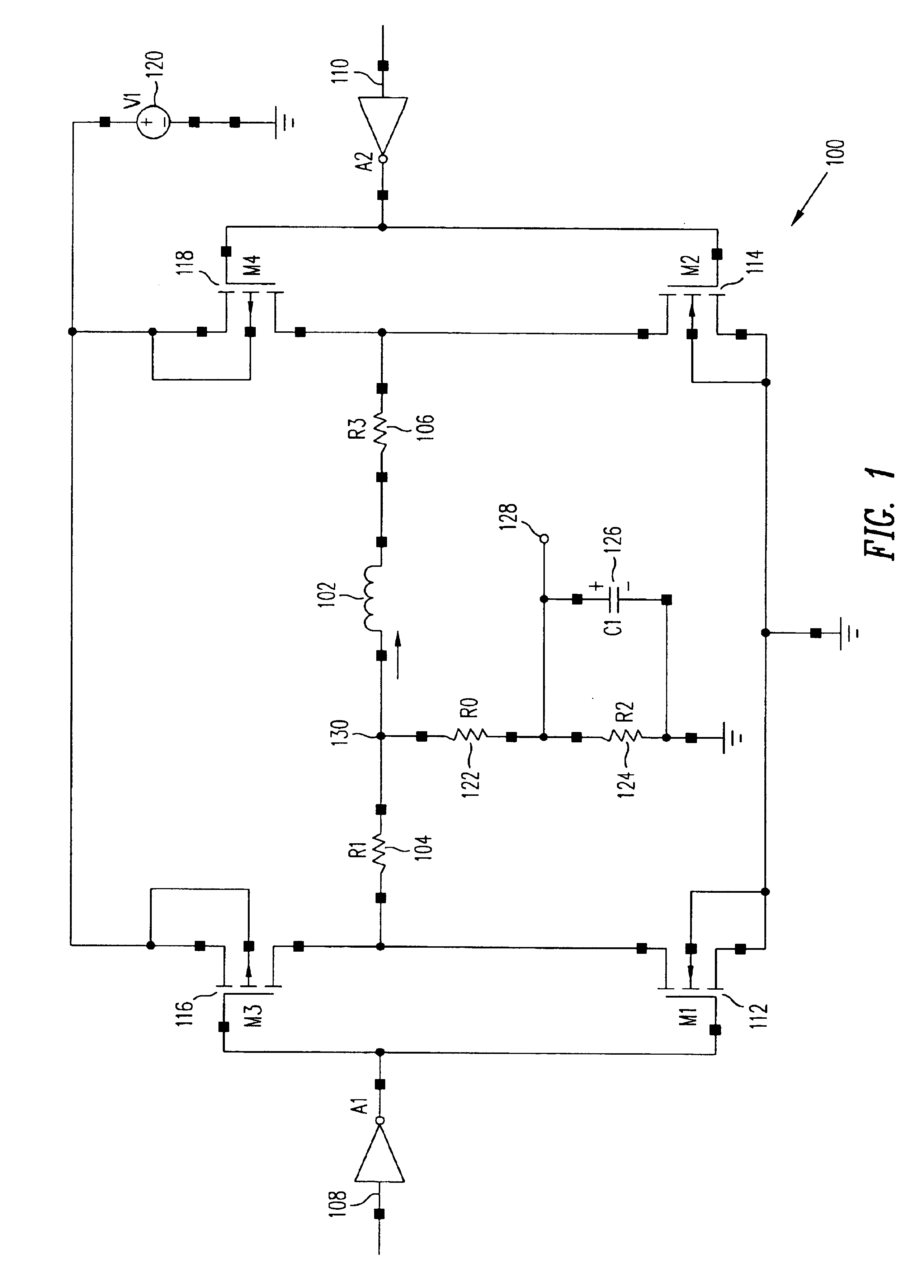
[0031]FIG. 1 shows a schematic representation of a voltage mode H configuration magnetic write head driver circuit 100 according to the present invention. As illustrated, the H configuration write driver circuit 100 is utilized to provide a bi-directional current flow through the externally connected write head 102 and the series resistors R1104 and R3106. In practice, inputs 108 and 110 through inverters A1 an A2 are used to control the conductivity of multiple field effect transistors (FETs) M1112, M2114, M3116 and M4118. When input 108 is set to V1 volts and input 110 is set to 0, the output of inverter A1 is 0 and the output of inverter A2 is V1. Then pFET M3116 and nFET M2114 are placed in a conductive state and nFET M1112 and pFET M4118 are in a nonconductive state. The voltage supply 120 causes current to flow through M3116, R1104, write head 102, R2106 and M4114 in a first direction from left to right. Alternatively, input 108 may be set to 0 and input 110 is set to V1 so th...

second embodiment

[0049]FIG. 7 shows a schematic representation of a current mode H configuration magnetic write head driver circuit 700 according to the present invention. The current mode driver circuit 700 is similar to the voltage mode driver circuit 100 shown in FIG. 1 excepting that series resistors R1 and R3 are eliminated and the source electrodes of nFETs M1 and M2112, 114 are connected to a current source I1710 instead of to ground. In current mode write driver 700, the current through the write head 102 is determined by the value of the current source 710. The voltage source V1120 provides bias voltage to the pFETs M3 and M4116, 118.

[0050]Operation of the current mode write driver 700 is the same as operation of the voltage mode write driver 100. As in the write driver 100, the resistors R0122, R2124 and capacitor C1126 connected between node 130 and ground are used to provide a voltage sense signal at output 128.

[0051]FIG. 8 is a timing diagram showing pictorial representations of the wav...


PUM

PropertyMeasurementUnit
frequencyaaaaaaaaaa
resistanceaaaaaaaaaa

Abstract

An open write head detection circuit is provided comprising a write head driver circuit, a programmable reference voltage source, a comparator and a pulse width filter. The write head driver circuit generates an voltage sense signal. The comparator compares the voltage sense signal with a reference voltage from the programmable reference voltage source and generates a comparator output signal indicative of whether the voltage sense signal is greater than or less than the reference voltage. The comparator output signal is input to the pulse width filter which generates a latched open head signal in response the voltage sense signal being less than the reference level for a predetermined time measured as a programmable number of write clock cycles.

Description

BACKGROUND OF THE INVENTION[0001]1. Field of the Invention[0002]This invention relates generally to head drive circuitry and in particular to an improved head drive circuit which includes open head or open cable detection. More particularly, the present invention relates to a magnetic tape recorder write head drive circuit which provides open head detection in a voltage or current mode write driver.[0003]2. Description of the Related Art[0004]Write head drive circuits having an H configuration are well known in the prior art. Such circuits are typically utilized in applications in which current is to be supplied in one of two directions to a load, such as a magnetic write recording head in a magnetic tape recorder or a magnetic disk drive. H write driver circuits are relatively fast and have generally low power dissipation.[0005]Reliability and serviceability are highly desirable characteristics in magnetic data recording systems for a computer memory system. It is important to dete...

Claims


Application Information

Patent Timeline
Patent Type & Authority Patents(United States)
IPC IPC(8): G11B5/02G11B5/008G11B5/455G11B5/00G11B27/36
CPCG11B5/00813G11B5/02G11B5/022G11B5/455G11B27/36G11B2005/0013G11B2220/20G11B2220/90
Inventor TRETTER, LARRY LEEROY
Owner IBM CORP
Why Eureka
Try Eureka