Vacuum arc eliminator having a bullet assembly actuated by a gas generating device

a gas generating device and vacuum arc eliminator technology, applied in emergency protective circuit arrangements, emergency protective circuit arrangements for limiting excess voltage/current, air-break switches, etc., can solve the problems of arcing fault inside the enclosure, arcing fault across the power bus of the motor control center (mcc), extreme hazard, etc., and achieve the effect of reducing the area of localized pressur

Inactive Publication Date: 2005-10-04
EATON CORP
View PDF10 Cites 15 Cited by
  • Summary
  • Abstract
  • Description
  • Claims
  • Application Information

AI Technical Summary

Benefits of technology

[0024]The bullet assembly includes a piston assembly and the lance. The bullet assembly piston assembly has a first side and a second side. Hereinafter, the first side will be the side exposed to the gas generating source and therefore may also be referred to as the pressure surface. The piston assembly pressure surface is not flat. As such, gas from the gas generating source is dispersed across the surface of the pressure surface thereby reducing areas of localized pressure. The pressure surface may be either concave or convex. Preferably, the pressure surface is convex, and, where the piston is circular, conical. The conical s

Problems solved by technology

There is the potential for an arcing fault to occur across the power bus of a motor control center (MCC), another low voltage (LV) enclosure (e.g., an LV circuit breaker panel), other industrial enclosures containing LV power distribution components, as well as medium voltage (MV) enclosures.
Frequently, a worker inadvertently shorts out the power bus, thereby creating an arcing fault inside the enclosure.
The resulting arc blast creates an extreme hazard and could cause injury or even death.
This problem is exacerbated by the fact that the enclosure doors are typically open for maintenance.
Thus, when the slug contacts both buses, the circuit is shorted.
Certain components, such as the bellows, are difficult and expensive to construct.
Prior art vacuum a

Method used


Image

  • Vacuum arc eliminator having a bullet assembly actuated by a gas generating device
  • Vacuum arc eliminator having a bullet assembly actuated by a gas generating device
  • Vacuum arc eliminator having a bullet assembly actuated by a gas generating device

Examples


Embodiment Construction

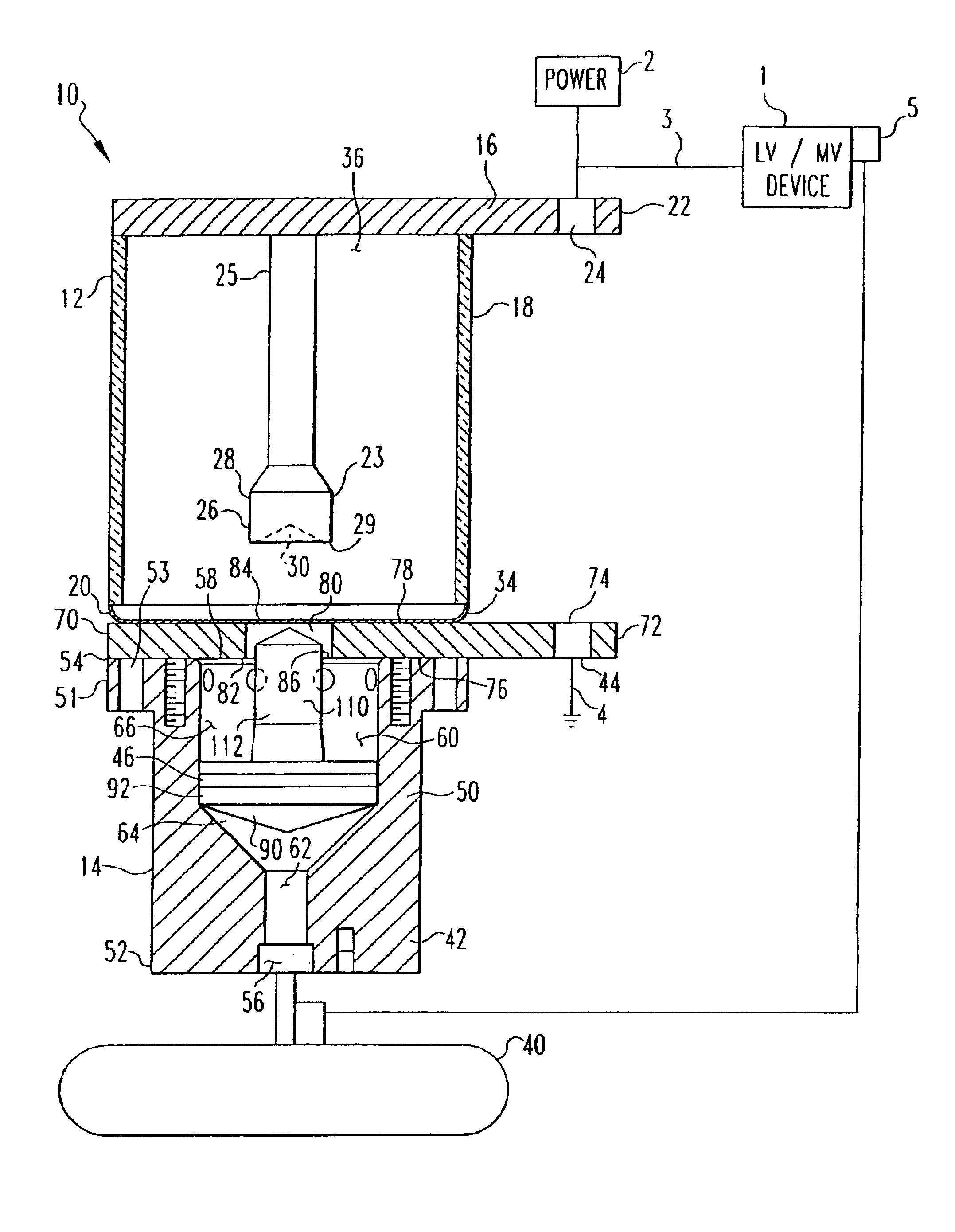
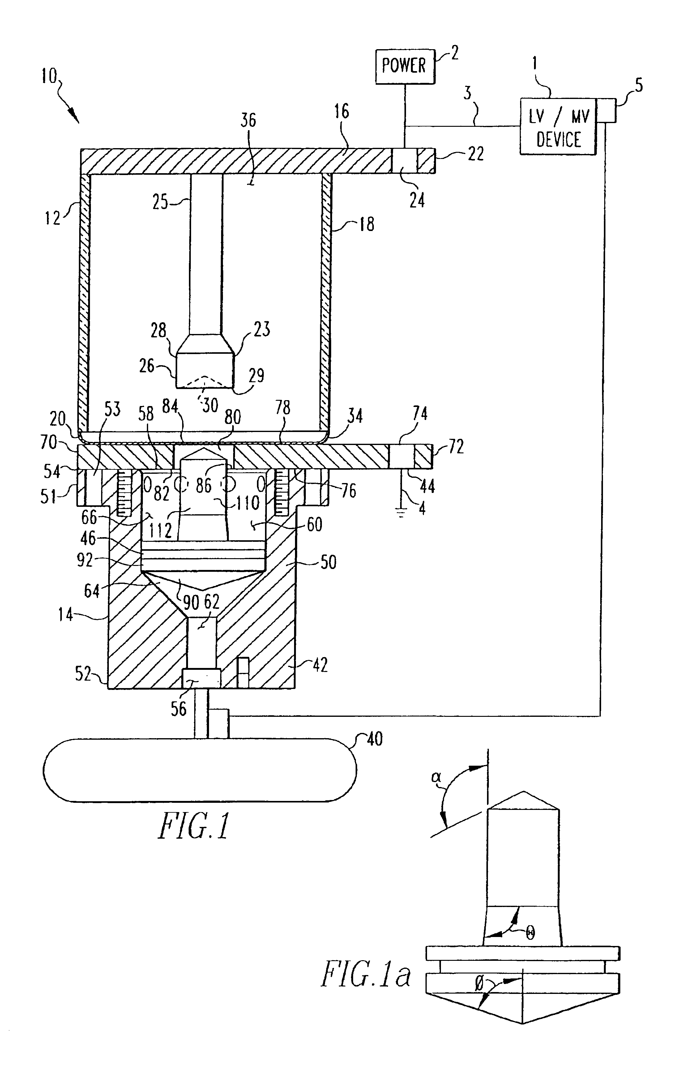
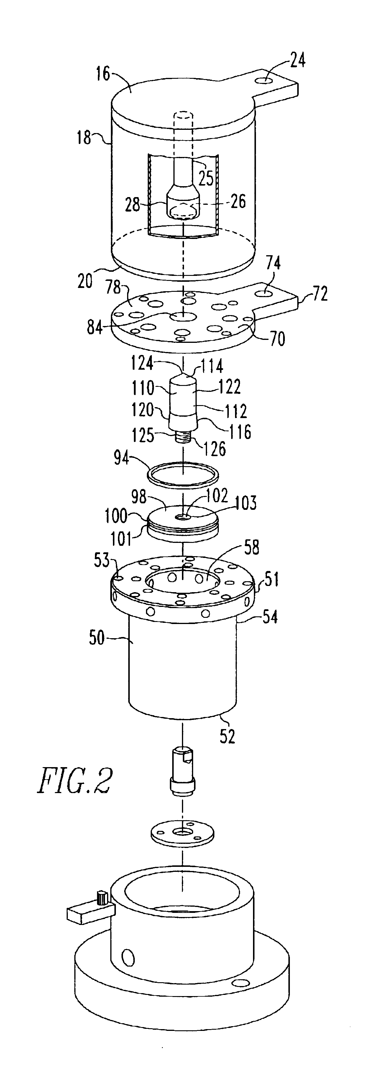
[0037]As shown in FIGS. 1-3, a vacuum arc interrupter 10 includes a vacuum chamber assembly 12 and a pressure chamber assembly 14. The vacuum chamber assembly 12 includes a first conductor 16, a non-conductive housing 18, and a seal cup 20. The first conductor 16 is made from a conductive material and, preferably, is shaped as a circular disk. The first conductor 16 may include a radial extension 22 having an attachment opening 24 therethrough. The attachment opening 24 is structured to allow a power line to be coupled to the first conductor 16. The first conductor 16 also includes an electrode 23 having a stem 25 and a receiving cup 26. The cup 26 is disposed at the distal end of the stem 25 and extends into the vacuum chamber 36 described hereinafter. The cup 26 is made from a conductive material and includes a continuous sidewall 28 having an open end 29, thereby defining a cavity 30. The cup 26 is supported by the stem 25 so that the cup 26 is spaced from the first conductor 16....


PUM


Abstract

A vacuum arc interrupter that includes a vacuum chamber assembly and a pressure chamber assembly. The vacuum chamber assembly includes a vacuum chamber and a first conductor which is structured to be coupled to a circuit. The first conductor is disposed within the vacuum chamber. The pressure chamber assembly has a second conductor structured to be coupled to a ground, a pressure chamber, a gas generation device and a bullet assembly. The pressure chamber assembly disposed adjacent to the vacuum chamber assembly. The gas generation device coupled to, and in fluid communication with the pressure chamber. The bullet assembly is disposed in the pressure chamber and structured to move between a first position, where the bullet assembly is spaced from the first and second conductors, and a second position, where the bullet assembly contacts, and is in electrical communication with, the first and second conductors.

Description

CROSS-REFERENCE TO RELATED APPLICATIONS[0001]This application is related to commonly assigned, concurrently filed:[0002]U.S. patent application Ser. No. 10 / 172,208 filed Jun. 14, 2002, entitled “Shorting Switch And System To Eliminate Arcing Faults In Power Distribution Equipment”, now U.S. Pat. No. 6,724,604;[0003]U.S. patent application Ser. No. 10 / 172,651, filed Jun. 14, 2002, entitled “Shorting Switch And System To Eliminate Arcing Faults In Power Distribution Equipment”, now U.S. Pat. No. 6,657,150;[0004]U.S. patent application Ser. No. 10 / 171,826, filed Jun. 14, 2002, entitled “Shorting Switch And System To Eliminate Arcing Faults In Low Voltage Power Distribution Equipment”, now U.S. Pat. No. 6,633,009;[0005]U.S. patent application Ser. No. 10 / 172,238, filed Jun. 14, 2002, entitled “Shorting Switch And System To Eliminate Arcing Faults In Power Distribution Equipment”;[0006]U.S. patent application Ser. No. 10 / 172,622, filed Jun. 14, 2002, entitled “Bullet Assembly For A Vacuu...

Claims


Application Information

Patent Timeline
IPC IPC(8): H01H33/66H01H33/28H01H33/666H01H33/32H01H39/00H01H79/00
CPCH01H33/32H01H33/666H01H33/6646H01H39/004H01H79/00
Inventor SLADE, PAUL G.TAYLOR, ERIK DANNELVANDER HEIDEN, MARY JO JOHNSON
Owner EATON CORP
Why Eureka
Try Eureka